Ion source with evaporator

An ion source and evaporator technology, applied in the field of ion sources with evaporators, can solve the problems of reduced evaporation rate, uneven distribution of materials to be evaporated, uneven material evaporation rate, etc.

Active Publication Date: 2018-06-19
ADVANCED ION BEAM TECHNOLOGY INC
View PDF5 Cites 0 Cited by
  • Summary
  • Abstract
  • Description
  • Claims
  • Application Information

AI Technical Summary

Problems solved by technology

[0011] Second, due to practical operational constraints, the temperature of the arc chamber may fluctuate even though the plasma temperature within the arc chamber 16 is not dynamically adjusted to provide ions with different energies / density
Therefore, the thermal energy transferred from the arc chamber 16 to the container 12 is inevitably unstable.
In addition, the heat provided by the heater 14 may also be unstable or uneven due to practical operating constraints.
Therefore, the material evaporation process in the evaporator 10 and the flow rate of the evaporated material from the evaporator 10 to the arc chamber 16 are often unstable, which inevitably affects the plasma in the arc chamber 16.
[0012] Third, evaporated material may condense on the transport path from container 12 to arc chamber 16 because both ends of channel member 13 may be indirectly heated by a heat source, such as arc chamber 16 and heater 14.
[0013] Fourth, the heat dissipated from the container 12 is usually uneven, and even somewhat uncontrollable, because of the limitations of the actual structure of the container 12, the shell 11 and other parts of the evaporator 10
Therefore, not only the evaporation rate of the material in the container 12 decreases due to heat dissipation, but also the evaporation rate of the material in the container 12 is not uniform.
Therefore, the function of the evaporator 10 is attenuated due to the actual heat dissipation
[0014] Fifth, the distribution of the material to be evaporated in the container 12 may also be uneven, especially the relative geometric relationship between the distribution of the stored material and the channel element 13
Therefore, the production of evaporated material in the gaseous state may also be non-uniform
[0015] Sixth, the use of an evaporator inevitably increases the cost and complexity of the ion source, especially when some parts of the evaporator can also be replaced when using different materials

Method used


Image

  • Ion source with evaporator
  • Ion source with evaporator
  • Ion source with evaporator

Examples


Embodiment Construction

[0074] A detailed description of the present invention will be discussed by means of the following examples, which are not intended to limit the scope of the present invention, but may be applicable in other applications. The drawings reveal some details, it must be understood that details of the design of the disclosed elements may differ from what has been disclosed, except in the case of explicit limitations on the characteristics of the elements.

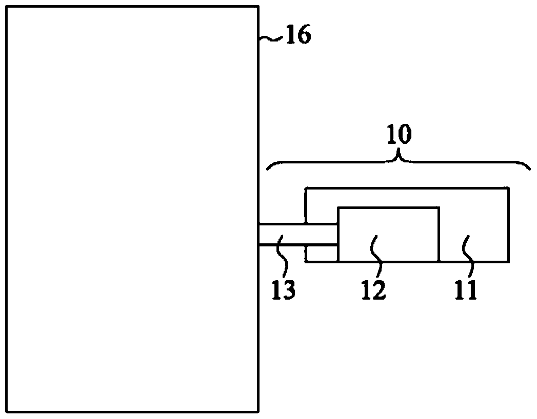
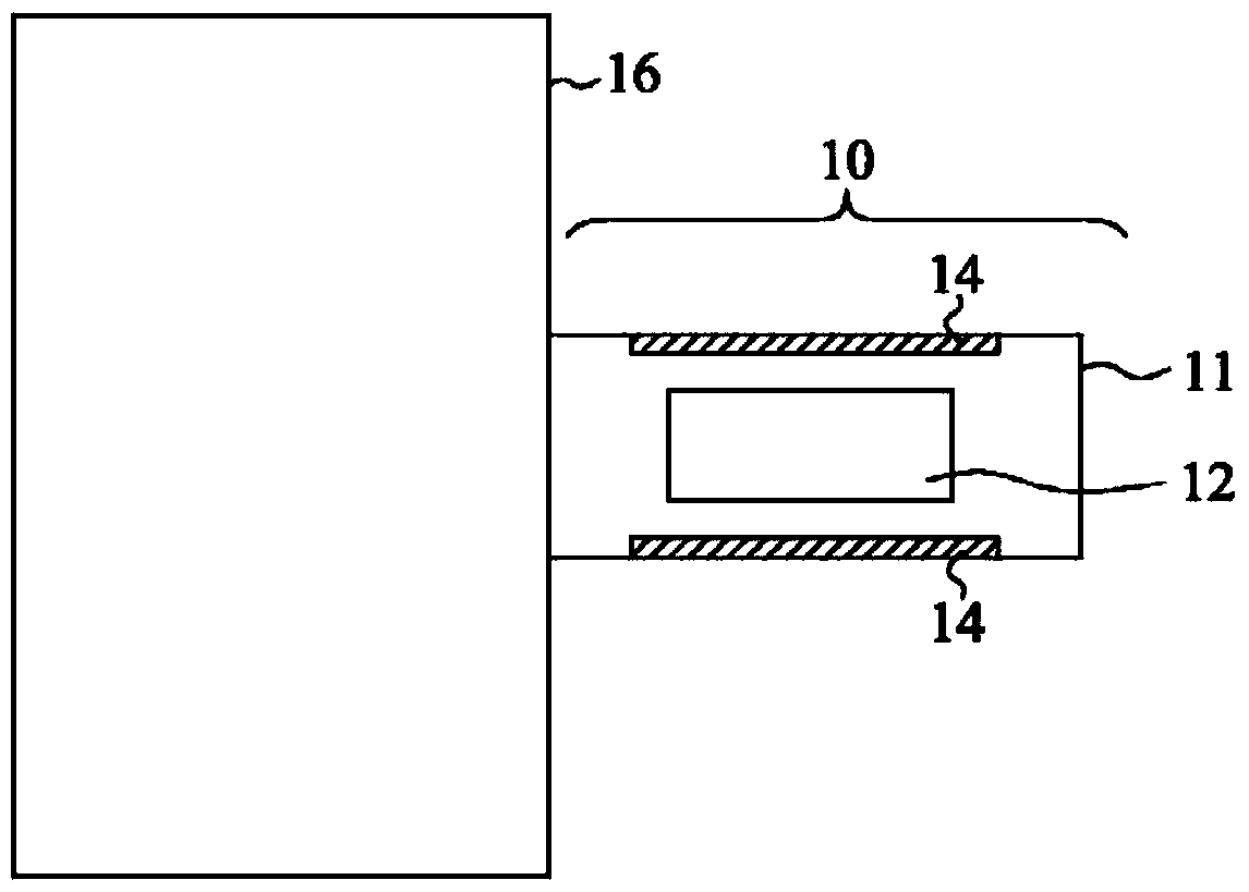
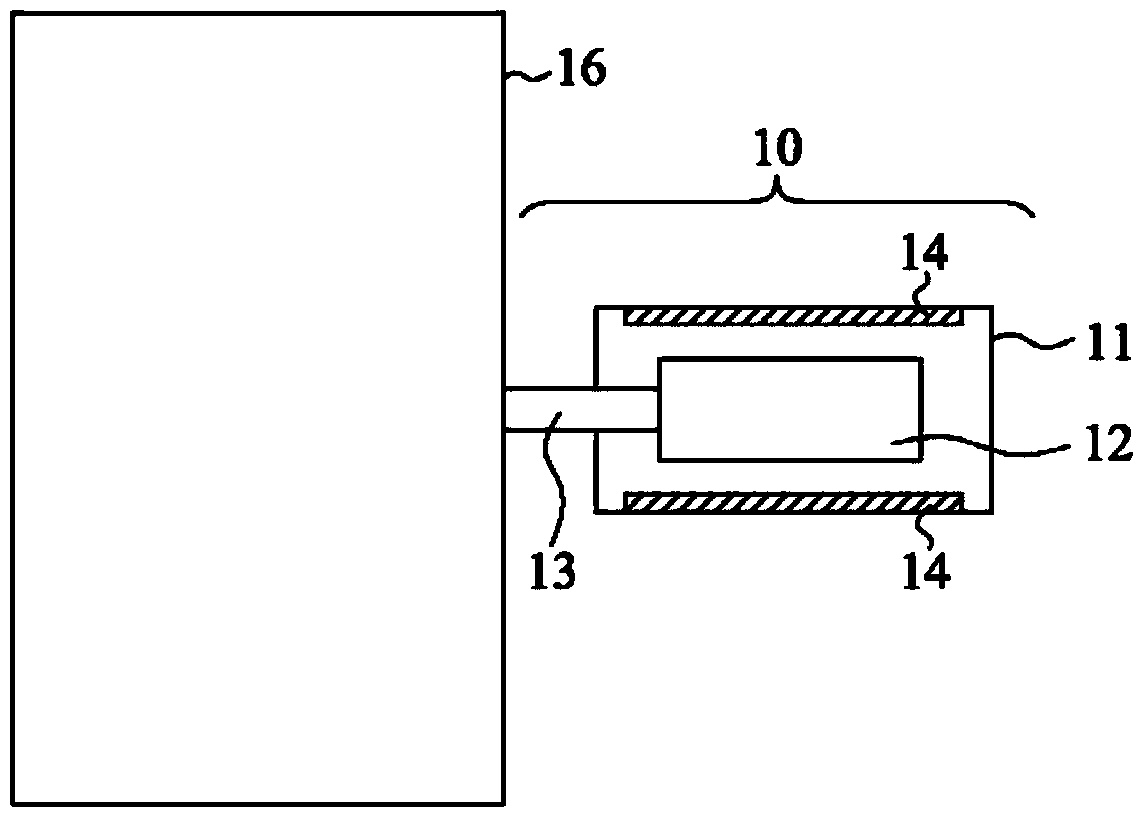
[0075] The ion source of an embodiment of the present invention is as Figure 2A and Figure 2B As shown, the evaporator 20 is disposed adjacent to the adjacent arc chamber 29 so that the material to be evaporated in the evaporator 20, whether solid or liquid, can be evaporated and then transferred into the arc chamber 29 so that the arc chamber 29 has a large amount of A plasma of ions of the desired species. In addition, the evaporator 20 has at least a housing 21 adjacent to the arc chamber 29, a container 22 arranged in th...


PUM


Abstract

The invention relates to an ion source with an evaporator; the ion source may have the evaporator, and uses the following one or more modes to reduce temperature difference in the evaporator; firstly, at least one heat insulator is arranged by partial a container and far away from a special heat source, wherein the container of the evaporator is heated by the special heat source; secondly, at least one heat insulator is arranged around the heater, wherein the container is arranged in the evaporator and heated by the heater; thirdly, at least one radiation shield is arranged so as to allow heat energy the pass the housing and a channel unit, wherein an arc chamber is connected with the housing through the channel unit in a machinery manner. The heat insulator can reduce heat energy loss, and the temperature difference in the evaporator is reduced; in addition, a hollow diffuser with a plurality of open pores is used for adding conductivity and reducing evaporated material condensation.

Description

technical field [0001] The present invention relates to an ion source, and more particularly to an ion source having a vaporizer that uses thermal insulators to reduce heat loss and / or uses a radiation shield with high thermal conductivity to conduct heat, Allows for more uniform temperature distribution within the evaporator, also particularly pertaining to an ion source having an evaporator that uses a hollow diffuser with a plurality of openings to convey evaporated material from a container within the evaporator to arc chamber. Background technique [0002] Ion implantation is a necessary but expensive process for modern device manufacturing technologies, such as semiconductor device manufacturing or flat panel manufacturing technology. Ion implantation is primarily used to dope-introduce chemically active species into a workpiece of semiconductor material, such as typically silicon. In most cases there is no other process that can replace ion implantation. There is a...

Claims


Application Information

Patent Timeline
Patent Type & Authority Patents(China)
IPC IPC(8): C23C14/48
CPCC23C14/48
Inventor 白晓胡扣霖荆泽陈丽暖万志民胡邵喻
Owner ADVANCED ION BEAM TECHNOLOGY INC
Why Eureka
Try Eureka