An Acoustic Resonance Thermally Driven Traveling Wave Thermoacoustic Refrigeration System

A traveling wave thermoacoustic and acoustic resonance technology, used in refrigerators, refrigeration and liquefaction, lighting and heating equipment, etc., can solve the problems of inconsistency of double-acting systems, no solution proposed, and increase of regenerator area. Achieve the effect of reducing irreversible heat loss, improving energy utilization, and eliminating moving parts

Active Publication Date: 2016-02-03
TECHNICAL INST OF PHYSICS & CHEMISTRY - CHINESE ACAD OF SCI +1
View PDF6 Cites 0 Cited by
  • Summary
  • Abstract
  • Description
  • Claims
  • Application Information

AI Technical Summary

Problems solved by technology

[0005] In 1998, at the beginning of the development of the traveling wave thermoacoustic engine, Yazaki and Iwata in Japan proposed an annular tube traveling wave thermoacoustic engine, such as figure 1 As shown, they used a laser Doppler velocimeter to measure the oscillation velocity of the working gas in the experiment, and realized that due to the large oscillation velocity of the working gas at the engine plate stack, it caused serious viscosity loss, which limited the traveling wave thermoacoustic engine. efficiency, but did not come up with a proper solution
[0006] Subsequently, the thermoacoustic Stirling heat engine proposed by Backhaus and Swift in the United States and some similarly structured thermoacoustic engines introduced a resonant tube structure, such as figure 2 As shown, although the system performance has been greatly improved, the resonant tube part is still dominated by the standing wave sound field, and a large part of the sound work of the thermoacoustic engine is dissipated in the resonant tube, and the introduction pole Greatly reduces the power density of the system
[0007] In 2010, KeesdeBlok in the Netherlands proposed a new type of 4th-order traveling wave thermoacoustic generator, whose structure is similar to that of Yazaki et al.’s annular tube traveling wave thermoacoustic engine, but the area of ​​the regenerator is increased, such as image 3 As shown, the oscillation velocity of the working gas is effectively reduced in the regenerator, which solves the problem of viscous loss in the regenerator of the annular tube traveling wave thermoacoustic engine of Yazaki et al.
However, the introduction of double-acting motors increases the problem of system inconsistency. When one of the motors is different from the other motors, this difference will be amplified in the loop and finally affect the performance of the system.
[0009] The present invention is based on the problems existing in the above thermoacoustic engine with resonant tube, loop traveling wave thermoacoustic engine, and double-acting thermoacoustic engine, and proposes a new design, which solves the problem of excessive resistance at the regenerator. The problem of large size and the volume of the resonance tube is too large, and it solves the problems of cold and heat loss and loop DC in the DeBlock loop system, and also solves the problem of inconsistency in the double-acting system

Method used


Image

  • An Acoustic Resonance Thermally Driven Traveling Wave Thermoacoustic Refrigeration System
  • An Acoustic Resonance Thermally Driven Traveling Wave Thermoacoustic Refrigeration System
  • An Acoustic Resonance Thermally Driven Traveling Wave Thermoacoustic Refrigeration System

Examples


Embodiment 1

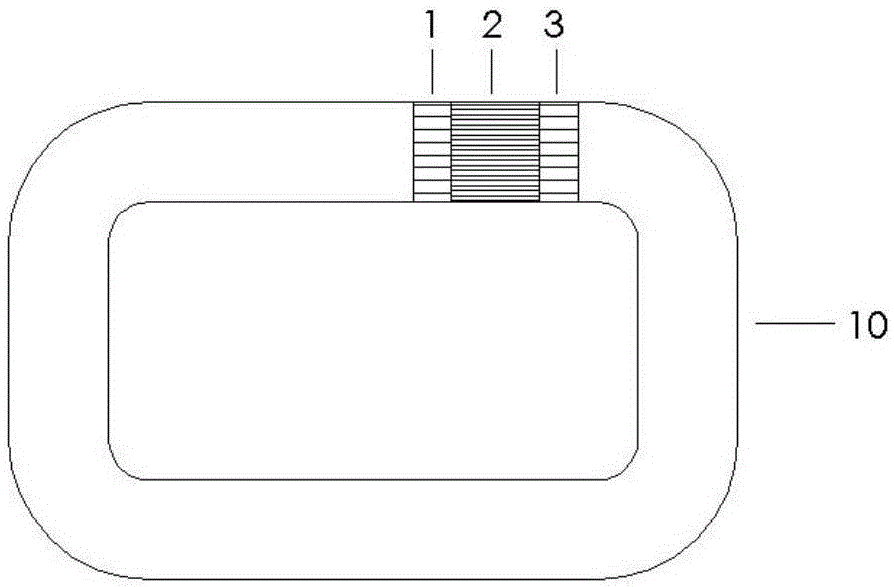
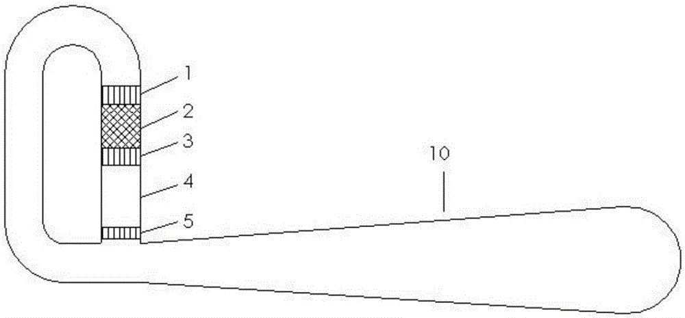
[0043] Figure 5 It is a structural schematic diagram of an acoustic resonance type heat-driven traveling wave thermoacoustic refrigeration system (embodiment 1) of the present invention; Figure 5 As shown, the thermoacoustic engine connected in series, the pulse tube refrigerator and the corresponding resonance tube constitute a thermoacoustic unit of the system. The loop acoustic resonance refrigeration system in this embodiment 1 is composed of three such thermoacoustic units connected end to end. As a result, the phase difference of the volume flow rate at the first and last ends of each thermoacoustic unit is 120°

[0044] Each thermoacoustic unit consists of the first main room temperature end heat exchanger 1, the first regenerator 2, the hot end heat exchanger 3, the first thermal buffer tube 4, and the second main room temperature end heat exchanger connected in series. 5. The second regenerator 6, the cold end heat exchanger 7, the second heat buffer pipe 8, the se...

Embodiment 2

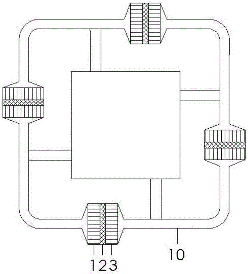
[0048] Image 6 It is a structural schematic diagram of a loop acoustic resonance refrigeration system (embodiment 2) of the present invention. Such as Image 6 As shown, the thermoacoustic engine connected in series, the pulse tube refrigerator and the corresponding resonant tube constitute a thermoacoustic unit of the system. The loop acoustic resonance refrigeration system in this embodiment 2 is composed of 4 such thermoacoustic units connected end to end. become.

[0049] In Embodiment 2, the phase difference of the volumetric flow rates at both ends of each thermoacoustic unit is 90°. Heat the heat exchanger 3 at the hot end, the first main room temperature heat exchanger 1, the second main room temperature heat exchanger 5 and the second room temperature heat exchanger 9 are fed with cooling water to maintain the room temperature range, when the hot end After the temperature gradient between the heat exchanger 3 and the first main room temperature heat exchanger 1 re...

Embodiment 3

[0051] Figure 7 It is a structural schematic diagram of a loop acoustic resonance refrigeration system (embodiment 3) of the present invention. Such as Figure 7 As shown, the thermoacoustic engine connected in series, the pulse tube refrigerator and the corresponding resonant tube constitute a thermoacoustic unit of the system. The loop acoustic resonance refrigeration system of this embodiment 3 is composed of 6 such thermoacoustic units connected end to end. become.

[0052] In Embodiment 3, the phase difference of the volumetric flow rates at both ends of each thermoacoustic unit is 60°. Heat the heat exchanger 3 at the hot end, the first main room temperature heat exchanger 1, the second main room temperature heat exchanger 5 and the second room temperature heat exchanger 9 are fed with cooling water to maintain the room temperature range, when the hot end After the temperature gradient between the heat exchanger 3 and the first main room temperature heat exchanger 1 ...


PUM


Abstract

The invention relates to an acoustic resonance type thermally-driven travelling wave thermo-acoustic refrigerating system. The acoustic resonance type thermally-driven travelling wave thermo-acoustic refrigerating system is composed of N elastic films and N thermo-acoustic units, wherein the thermo-acoustic units are connected end to end through resonance tubes and form an annular loop, N is a positive integer ranging from 3 to 10, and the phase difference of volume flow rates of the two ends of each thermo-acoustic unit is 360 degrees / N. Each thermo-acoustic unit is composed of a thermo-acoustic engine and a pulse tube refrigeration machine. No movable parts are arranged in the refrigerating system, and reliability of the refrigerating system is further improved. Pure travelling wave phase positions can be obtained in an acoustic resonance loop system, acoustic power flowing out of each thermo-acoustic unit through the corresponding pulse tube refrigeration machine is recycled by the next thermo-acoustic unit, and therefore work efficiency of the system can be further improved. In addition, different numbers of thermo-acoustic units can be connected in series according to the required cooling capacity condition so that large-cooling-capacity output can be achieved. The acoustic resonance type thermally-driven travelling wave thermo-acoustic refrigerating system is large in cooling capacity, high in efficiency, long in service life and simple in structure, and has good application prospects in places where the requirements for cooling capacity are high.

Description

technical field [0001] The invention relates to a refrigeration system, in particular to a novel acoustic resonance heat-driven traveling wave thermoacoustic refrigeration system. Background technique [0002] With the application of high-temperature superconductivity, superconducting transformers, superconducting generators, superconducting motors, superconducting cables, current limiters, and superconducting energy storage have achieved rapid development. further requirements. At present, there are still some unresolved problems in high-power pulse tube refrigerators. Due to the increase in size, it is easy to cause uneven gas flow and temperature distribution, and it is difficult to further increase the power. At present, there is no good solution. On the other hand, with the increasing consumption of oil and coal resources and the increasing environmental pollution, increasing the proportion of natural gas in primary energy has become an important way to optimize the en...

Claims


Application Information

Patent Timeline
Patent Type & Authority Patents(China)
IPC IPC(8): F25B23/00
Inventor 罗二仓童欢陈燕燕戴巍张丽敏
Owner TECHNICAL INST OF PHYSICS & CHEMISTRY - CHINESE ACAD OF SCI
Why Eureka
Try Eureka