Electromagnetically-assisted laser drilling method and device

A technology for assisting laser and punching devices, which is used in laser welding equipment, welding equipment, metal processing equipment, etc. It can solve the problem that laser welding units cannot be used for laser drilling, impact hole repetition accuracy is low, and plasma shielding effect is serious, etc. It can fully absorb the energy of laser action, improve the punching efficiency, and reduce the loss of laser energy.

Active Publication Date: 2014-05-28
上海尚朴光电技术有限公司
View PDF9 Cites 33 Cited by
  • Summary
  • Abstract
  • Description
  • Claims
  • Application Information

AI Technical Summary

Problems solved by technology

However, the existing laser drilling method has the following disadvantages: 1. The plasma shielding effect is serious in the laser drilling process, which causes the loss of laser energy; 2. There is a recast layer with uneven thickness on the hole wall after processing, which affects the quality of the hole; 3. The impact force generated during the high-energy and long-pulse laser drilling process is too large, resulting in low repeatability of the processed holes, micro-cracks on the hole wall, and difficult to improve the quality of the holes.
[0004] Although there are methods and units for magnetic field-assisted laser welding in the prior art (such as the Chinese invention patent No. 200410101556.6 "A Magnetic Field-Assisted Laser Welding Unit"), due to the different characteristics of laser welding and drilling, laser welding Soldered units are not suitable for laser drilling

Method used


Image

  • Electromagnetically-assisted laser drilling method and device
  • Electromagnetically-assisted laser drilling method and device
  • Electromagnetically-assisted laser drilling method and device

Examples


Embodiment Construction

[0037] The details and working conditions of the method and device proposed by the present invention will be described in detail below in conjunction with the accompanying drawings and embodiments. It should be understood that the specific embodiments described here are only used to explain the present invention, not to limit the present invention.

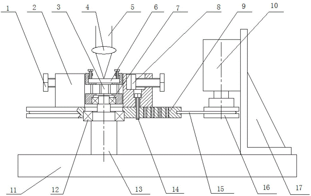
[0038] The invention provides an electromagnetic-assisted laser drilling device (such as figure 1 with figure 2 As shown), it includes four parts, which are laser generating unit, workpiece clamping unit, rotating magnetic field generating unit and driving unit.

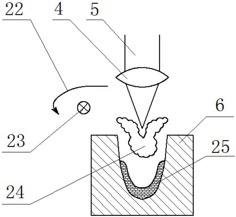
[0039] The laser generating unit includes a laser and a focusing lens 4, and the laser beam output by the laser is focused by the focusing lens 4 and acts on the surface of the workpiece 6 to be processed;

[0040] The workpiece clamping unit includes a main shaft 13, a base plate 11, a first bearing 7 and a squirrel cage 3, wherein the main shaft 13 is fixedly instal...


PUM


Abstract

The invention provides an electromagnetically-assisted laser drilling method. The method includes the steps of 1, clamping a workpiece to be processed onto an electromagnetically-assisted laser drilling device; 2, driving a fixture base to rotate by a motor so that a permanent magnet clamped on the fixture base rotates at high speed and forms a rotational magnetic field; meanwhile, allowing a mouse cage in the rotational magnetic field to produce electromagnetic force whereby the workpiece rotates in sync with the mouse cage; 3, after the speed of the motor stabilizes to a preset value, starting a laser, which generates a laser beam acting on the surface of the workpiece via a focusing lens so as to finish the electromagnetically-assisted laser drilling process. According to the method, the application of the operating method of rotating the workpiece enhances the assistance of the magnetic field in laser drilling; meanwhile, the rotational magnetic field can control motion of plasma and molten metal generated in the laser drilling process, so that laser drilling effect is optimized. The invention further provides the electromagnetically-assisted laser drilling device.

Description

technical field [0001] The invention belongs to the field of laser processing, and in particular relates to an electromagnetic-assisted laser drilling method and device. Background technique [0002] In mechanical processing, hole processing is an important processing procedure with a relatively large proportion. With the miniaturization of parts and mass production, it is difficult for ordinary mechanical drilling methods to realize the manufacture of large quantities of small holes and micro holes. Laser Drilling is one of the key technologies in the field of modern manufacturing technology. Compared with other drilling methods, laser drilling has a large depth-to-diameter ratio, no contact, no tool loss, fast processing speed, small surface deformation, and can process various Material and other significant advantages, can well meet the requirements of modern industrial product processing, has been widely used, such as the processing of cooling holes of worm gear blades o...

Claims


Application Information

Patent Timeline
Patent Type & Authority Applications(China)
IPC IPC(8): B23K26/00B23K26/70
CPCB23K26/0823B23K26/16B23K26/382
Inventor 冯爱新卢轶薛伟吴川罗敬文曹宇瞿建武曹宇鹏朱德华温德平
Owner 上海尚朴光电技术有限公司
Why Eureka
Try Eureka