Supercharge Your Innovation With Domain-Expert AI Agents!

Oil-sludge-water separation device

A separation device and mud-water separation tank technology, applied in liquid separation, separation method, grease/oily substance/float removal device, etc., can solve problems such as poor separation effect, achieve small footprint, good effect, and fast separation speed Effect

Active Publication Date: 2014-05-28
SHANDONG HYGIYA ENVIRONMENTAL PROTECTION EQUIP
View PDF9 Cites 6 Cited by
  • Summary
  • Abstract
  • Description
  • Claims
  • Application Information

AI Technical Summary

Problems solved by technology

[0004] The invention provides A new type of oil, mud and water separation device, which can not only effectively prevent pollutants in highly turbid and oily sewage from staining the filter material and clogging the filter element, but also realize continuous and normal operation of the oil, mud and water separation device. And can ensure the oil, mud, water separation effect is stable

Method used


Image

  • Oil-sludge-water separation device
  • Oil-sludge-water separation device
  • Oil-sludge-water separation device

Examples


Embodiment Construction

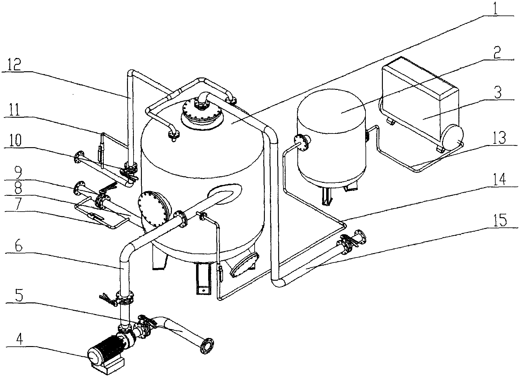
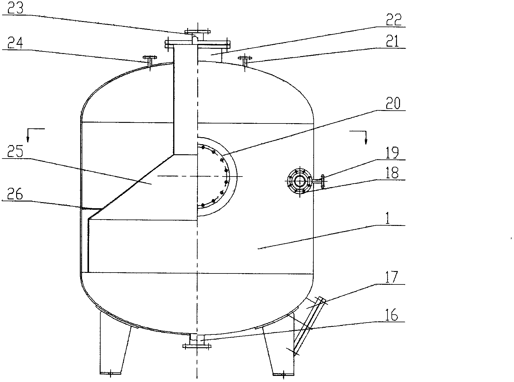
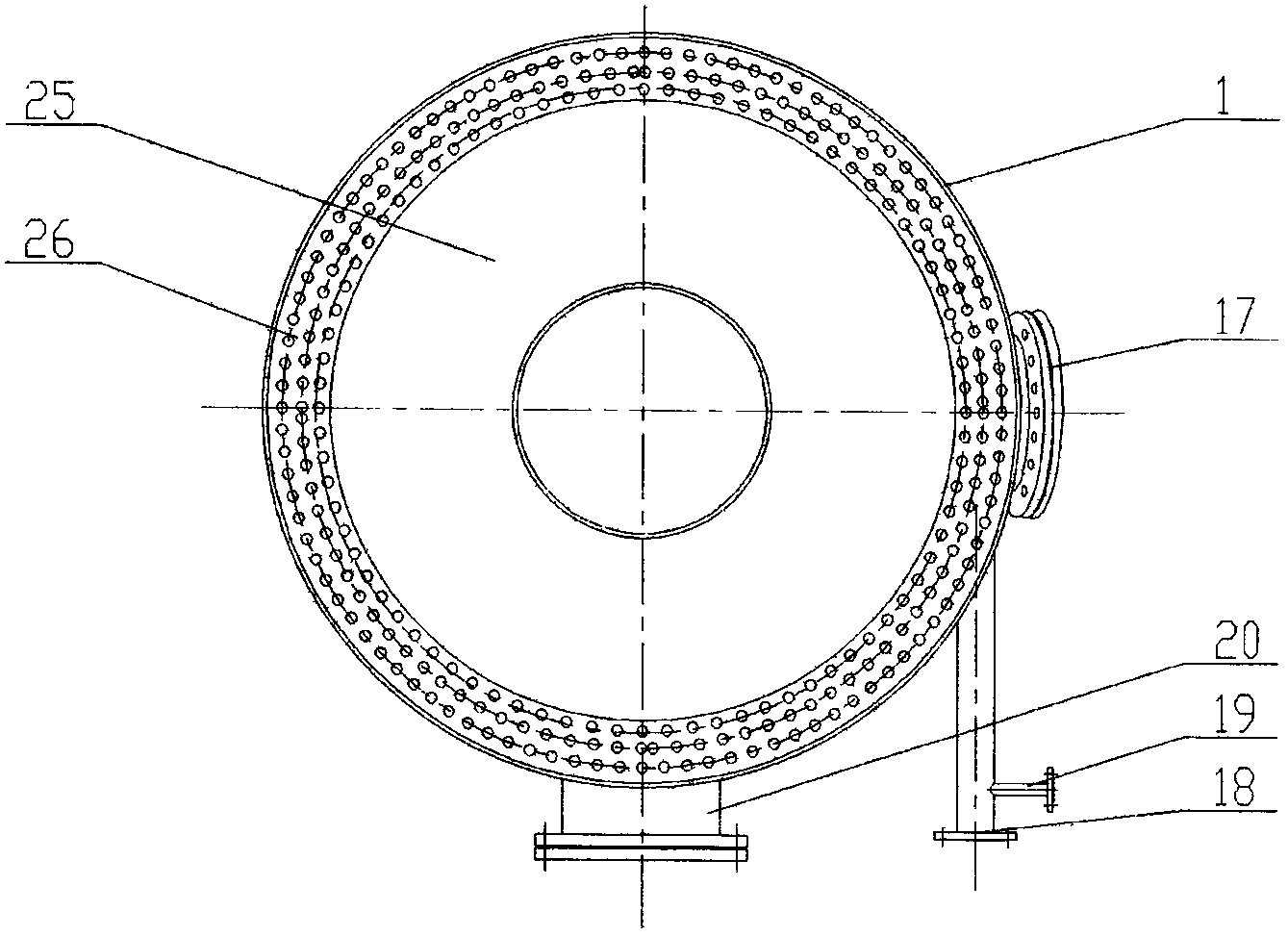
[0015] 1. in figure 1 Among them, the liquid inlet (18) on the sludge water separation tank (1) is connected to the outlet of the lift pump (4) through the lift pump outlet manifold (6), and the inlet of the lift pump (4) is connected through the lift pump inlet manifold (5) It is connected with the liquid container device to be treated (not shown); the pipe joint of the liquid inlet (18) of the oil sludge water separation tank is equipped with a gas-dissolving port (19), and the gas-dissolving port (19) is separated from the sludge water through the gas storage tank The gas filling connecting pipe (14) of the tank is connected with the gas outlet of the gas storage tank (2), and the air inlet of the gas storage tank (2) is connected to the air supply connecting pipe (13) of the gas storage tank through an air compressor. The air outlet of the machine (3) is connected; the oil collection port 1 (21) and the oil collection port 2 (24) on the sludge water separation tank (1) are...


PUM


Abstract

The invention discloses an oil-sludge-water separation device. The oil-sludge-water separation device is characterized in that the device comprises an oil-sludge-water separation tank, a gas storage tank, an air compressor, a lift pump and connecting manifolds. The device is a vertical circular tank assembly, and the operation only requires gas filling instead of dosing; during operation, a liquid to be separated is lifted and boosted through the lift pump, the lifted and boosted liquid then enters the oil-sludge-water separation tank after a gas is dissolved in the manifolds, and oil, sludge and water in the incoming liquid are separated from one another in the oil-sludge-water separation tank through the synergy of the six technical principles of centrifugation, gas floatation, coagulation, micro-vortex, gravity and inertia. The device has the advantages of continuous operation with one input and three outputs, high separation speed, good separation effect, and low operating cost, and is the optimum choice for the oil-sludge-water separation of output liquids from high-water-cut oil fields and high-turbidity oily sewage.

Description

Technical field [0001] The invention relates to an oil, mud and water separation device, in particular to an oil, mud and water separation device for high water content oil field output liquid and high turbid oily sewage. Background technique [0002] Most of the oil, mud and water separation devices used in oilfields use large tanks for dosing and settling. After a long period of settling in the tanks, the oil floats on the top of the tank, the mud and sand settle to the bottom of the tank, and the water exists in the middle. This method has a large volume of equipment. , large area, long settling time, high operating cost of dosing, low efficiency, large amount of sludge formed, drug pollution to oil, water and the environment, and difficult to clean up the sludge settled at the bottom of the tank. [0003] In order to solve this problem, an integrated continuous flow oily sewage treatment device (patent number: ZL2008 1 0169325.7) was carried out to carry out the separati...

Claims


Application Information

Patent Timeline
Patent Type & Authority Applications(China)
IPC IPC(8): C02F1/40C02F1/38
Inventor 张瑾张后继刘宝吴开秀颜东华任召芳
Owner SHANDONG HYGIYA ENVIRONMENTAL PROTECTION EQUIP
Features
  • R&D
  • Intellectual Property
  • Life Sciences
  • Materials
  • Tech Scout
  • Unparalleled Data Quality
  • Higher Quality Content
  • 60% Fewer Hallucinations
Learn More