Particle drying machine

A particle drying and motor technology, which is applied in the direction of dryers, drying, lighting and heating equipment, etc., can solve the problems of large loss and achieve the effects of small loss, easy promotion and use, and high efficiency

Inactive Publication Date: 2014-05-28
NANTONG YUANYA PRECISION MACHINERY
View PDF5 Cites 3 Cited by
  • Summary
  • Abstract
  • Description
  • Claims
  • Application Information

AI Technical Summary

Problems solved by technology

Most of the traditional dryers for drying solid granules remove the moisture content in the granules by heating and stirring continuously after feeding the materials. It works well for granules with high surface hardness; but for light and hard granules For the particles

Method used


Image

  • Particle drying machine

Examples


Embodiment Construction

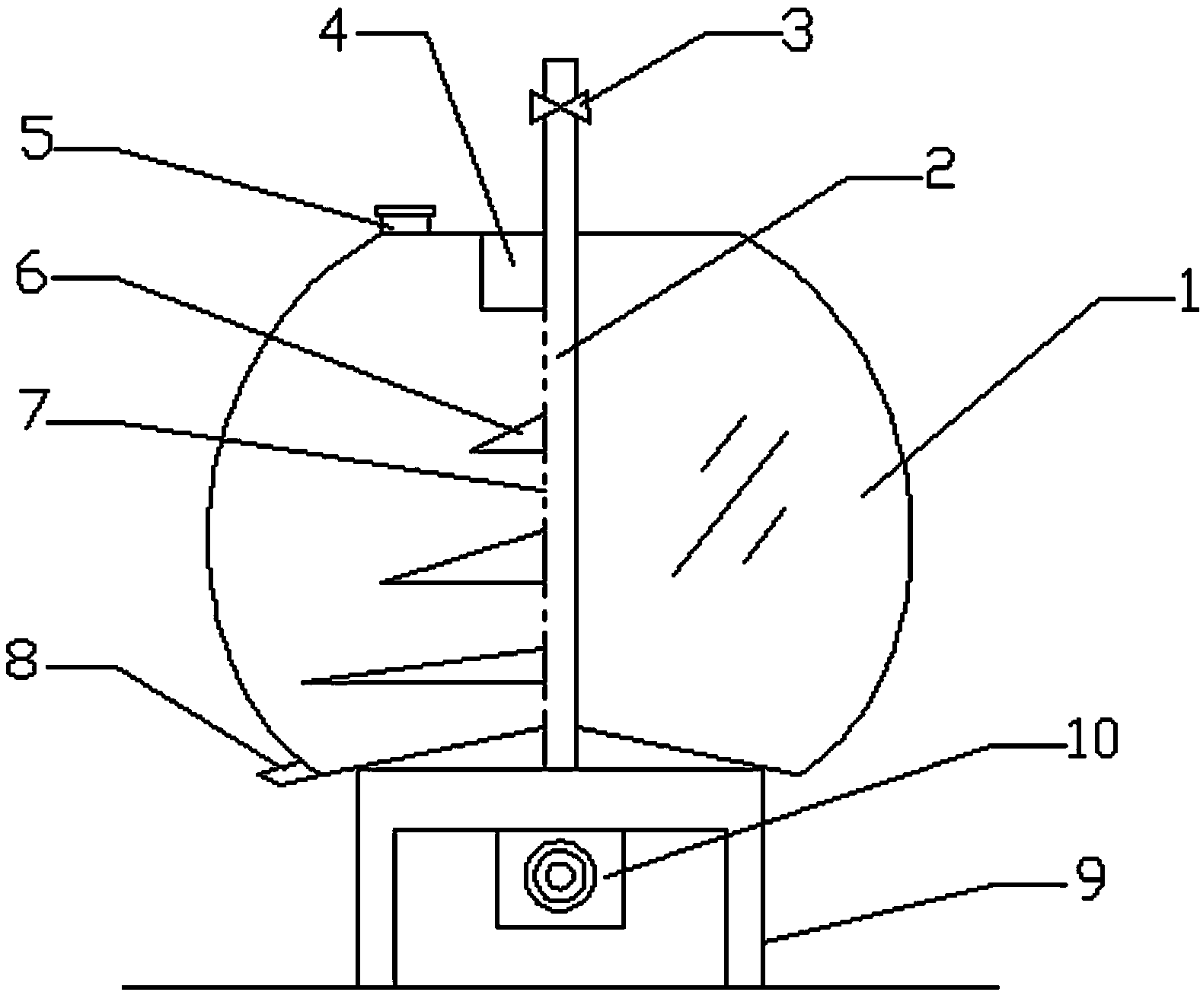
[0014] Such as figure 1 As shown, a particle dryer includes a box body 1 and a bracket 9, the box body 1 is supported on the bracket 9; it also includes a stirring shaft 2, a feed channel 4 and a discharge channel 8, the stirring shaft 2 passes through the box body 1 The interior is fixedly connected with the motor 10, the motor 10 is fixed on the bracket 9, and the stirring shaft 2 located in the upper part of the box 1 is provided with a valve 3 for controlling the flow rate of the air flow. The valve 3 is fixedly connected with the hot air blower; The stirring shaft 2 is provided with a plurality of stirring paddles 6 and pore groups 7 distributed at intervals. Each stirring paddle 6 is in the shape of a cone, and the bottom radius increases sequentially from top to bottom; the feed channel 4 is fixed on the top of the box 1 , The bottom of which is a screen; the discharge channel 8 is provided at the junction of the bottom and the side of the box body 1; the top of the box...


PUM


Abstract

The invention provides a particle drying machine. The particle drying machine comprises a box and a support, wherein the box is supported on the support. The particle drying machine further comprises a stirring shaft, a feed passage and a discharge passage. The stirring shaft penetrates through the interior of the box and is fixedly connected with a motor. The motor is fixed to the support. A valve for controlling the airflow rate is arranged on the portion, above the box, of the stirring shaft. The valve is fixedly connected with a hot air supply system. A plurality of stirring paddles arranged at intervals and an air hole set are arranged on the portion, inside the box, of the stirring shaft. Each stirring paddle is in a cone shape. The radii of the bottoms of the stirring paddles increase sequentially from top to bottom. The feed passage is fixed to the top of the box. The discharge passage is arranged at the junction between the bottom of the box and the side face of the box. The top of the box is provided with an air outlet. The particle drying machine has the advantages of being capable of fully drying light and hard particles, short in drying time, high in drying efficiency, little in particle loss and convenient to popularize and use.

Description

Technical field [0001] The invention relates to a dryer, in particular to a particle dryer. Background technique [0002] Dryer is a kind of mechanical equipment that uses heat energy to reduce the moisture content of the materials. It vaporizes and escapes the moisture or other volatile liquid components in the materials through the addition of heat sources to obtain solid materials with specified moisture content. The need for use or further processing. The traditional dryers used to dry solid particles mostly remove the wet components in the particles by heating and continuous stirring after passing the materials. The effect is good for particles with larger surface hardness; but for light, light and hard particles As for the particles, it is very easy for the repeated friction between the particles and the friction between the particles and the stirring device during the stirring process to cause excessive loss. Therefore, it is necessary to propose a new technical solution ...

Claims


Application Information

Patent Timeline
IPC IPC(8): F26B17/00
Inventor 张华
Owner NANTONG YUANYA PRECISION MACHINERY
Why Eureka
Try Eureka