Unsmooth dynamic compensation method for ultralow-frequency horizontal vibration table guide rail

A technology of dynamic compensation and vibrating table, which is applied in the direction of measuring ultrasonic/sonic/infrasonic waves, measuring devices, instruments, etc. It can solve the problems of increasing the stroke of the vibrating table, high cost of implementation, and difficulty in meeting the requirements of reducing the accuracy of the guide rail. , The compensation effect is obvious, and the effect of convenience is realized

Active Publication Date: 2014-05-28
ZHEJIANG UNIV
View PDF7 Cites 22 Cited by
  • Summary
  • Abstract
  • Description
  • Claims
  • Application Information

AI Technical Summary

Problems solved by technology

Under ultra-low frequency conditions, the sinusoidal vibration acceleration component applied horizontally to the vibrating table and the gravitational acceleration component generated by the pitching of the moving parts (in the present invention only refers to the direction along the sensitive axis of the sensor to be calibrated, the same below) have similar amplitudes, so that The calibration principle of single-axis sinusoidal steady-state excitation is not satisfied, and it also brings difficulties and deviations to the extraction and processing of signals
It is easy to ensure the straightness of t

Method used


Image

  • Unsmooth dynamic compensation method for ultralow-frequency horizontal vibration table guide rail
  • Unsmooth dynamic compensation method for ultralow-frequency horizontal vibration table guide rail
  • Unsmooth dynamic compensation method for ultralow-frequency horizontal vibration table guide rail

Examples


Embodiment 1

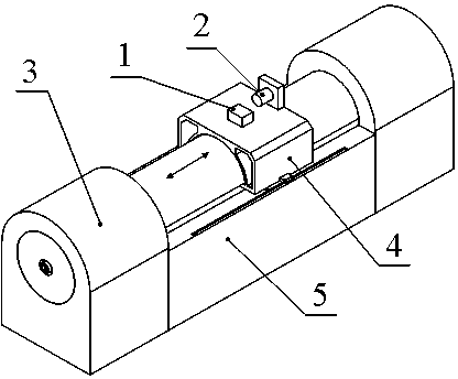
[0034] This embodiment uses an angle sensor to measure the pitch angle of the moving part (sliding table) of the shaking table to obtain the dynamic characteristics of the unevenness of the guide rail of the shaking table as an example. figure 1 shown.

[0035] A method for dynamically compensating for the unevenness of the guide rail of an ultra-low frequency horizontal vibrating table, comprising the following steps:

[0036] (1) Real-time measurement of the dynamic characteristics of the guide rail irregularity of the ultra-low frequency horizontal vibration table 3 , with the output of the schooled acceleration sensor 2 u ori ( t ):

[0037] (1.1), install the angle sensor 1 on the sliding table 4 of the vibration table, and use the horizontal direction as the reference direction to detect the change of the pitch angle during the movement of the sliding table; at the same time, install the acceleration sensor 2 to be calibrated on the vibration table On the sliding ...

Embodiment 2

[0055] The difference between this embodiment and Embodiment 1 is that a laser vibrometer is used to detect the pitch angle of the sliding table of the vibrating table due to the unevenness of the guide rail during the vibration calibration process based on the method of synchronous measurement of two lasers, and obtain the unevenness of the guide rail. Smoothness θ ( t ) as an example.

[0056] A method for dynamically compensating for the unevenness of the guide rail of an ultra-low frequency horizontal vibrating table, comprising the following steps:

[0057] (1) Real-time measurement of the dynamic characteristics of the guide rail irregularity of the ultra-low frequency horizontal vibration table 3 , with the output of the schooled acceleration sensor 2 u ori ( t ):

[0058] (1.1), such as Figure 4 As shown, the laser reflector frame 6 vertically installed on the slide table 4 is equipped with two reflectors, the laser vibrometer 7 and the laser vibrometer 8 are ...


PUM


Abstract

The invention discloses an unsmooth dynamic compensation method for an ultralow-frequency horizontal vibration table guide rail. The unsmooth dynamic compensation method comprises the following steps: measuring unsmooth dynamic characteristics of the ultralow-frequency horizontal vibration table guide rail and output uori t of a calibrated acceleration sensor in real time by taking a horizontal direction as reference; constructing a guide rail unsmoothness dynamic compensation system, and removing a gravitational acceleration component in the output of the calibrated sensor generated by pitching of a sliding table from the original output of the calibrated sensor in real time in the vibration calibration process; calibrating a calibrated acceleration sensor by adopting the compensated output ucomt of the calibrated sensor, calculating to obtain a compensated amplitude-frequency curve, and finishing vibration calibration of the calibrated sensor. The unsmooth dynamic compensation method has the advantages that the calibration result deviation of the acceleration sensor with zero frequency response caused by guide rail unsmoothness based on the ultralow-frequency horizontal vibration table can be compensated in real time in the vibration calibration process, so that the precision of ultralow-frequency vibration calibration is improved.

Description

technical field [0001] The invention relates to a dynamic compensation method for the irregularity of the guide rail of an ultra-low frequency horizontal vibrating table. technical background [0002] With the continuous development of science and technology, the problem of ultra-low frequency vibration traceability needs to be solved urgently. For example, the measurement lower limit of various vibration sensors widely used in aerospace, building monitoring, earthquake prediction, resource exploration and other fields is mostly lower than 0.1Hz, or even As low as zero frequency, accurate calibration of the relevant characteristics of these ultra-low frequency vibration sensors is a prerequisite for their correct application. Therefore, people's demand for ultra-low frequency vibration calibration systems is becoming more and more urgent. [0003] The ultra-low-frequency vibration table is an important part of the ultra-low-frequency vibration calibration system. Its functio...

Claims


Application Information

Patent Timeline
IPC IPC(8): G01H17/00
Inventor 何闻张旭飞王春宇贾叔仕
Owner ZHEJIANG UNIV
Why Eureka
Try Eureka