Fault branch identification method and apparatus for multi-terminal DC line protection

A technology of multi-terminal DC and discrimination method, which is applied in the direction of emergency protection circuit devices, fault locations, power transmission AC networks, etc., can solve the problems of high cost, equipment footprint and large investment, and achieve high accuracy and save land occupation , The effect of simplifying the line structure

Active Publication Date: 2014-05-28
CHINA ENERGY ENG GRP GUANGDONG ELECTRIC POWER DESIGN INST CO LTD
View PDF4 Cites 5 Cited by
  • Summary
  • Abstract
  • Description
  • Claims
  • Application Information

AI Technical Summary

Problems solved by technology

[0005] One of the purposes of the present invention is to provide a method for discriminating the fault branch of the multi-terminal DC line protection in order to solve the problems of the above-mentioned prior art equipment with large footprint, large investment and high cost. Setting the current transformer can realize the discrimination of the fault branch, which reduces the configuration of hardware equipment and saves engineering investment

Method used


Image

  • Fault branch identification method and apparatus for multi-terminal DC line protection
  • Fault branch identification method and apparatus for multi-terminal DC line protection
  • Fault branch identification method and apparatus for multi-terminal DC line protection

Examples


specific Embodiment 1

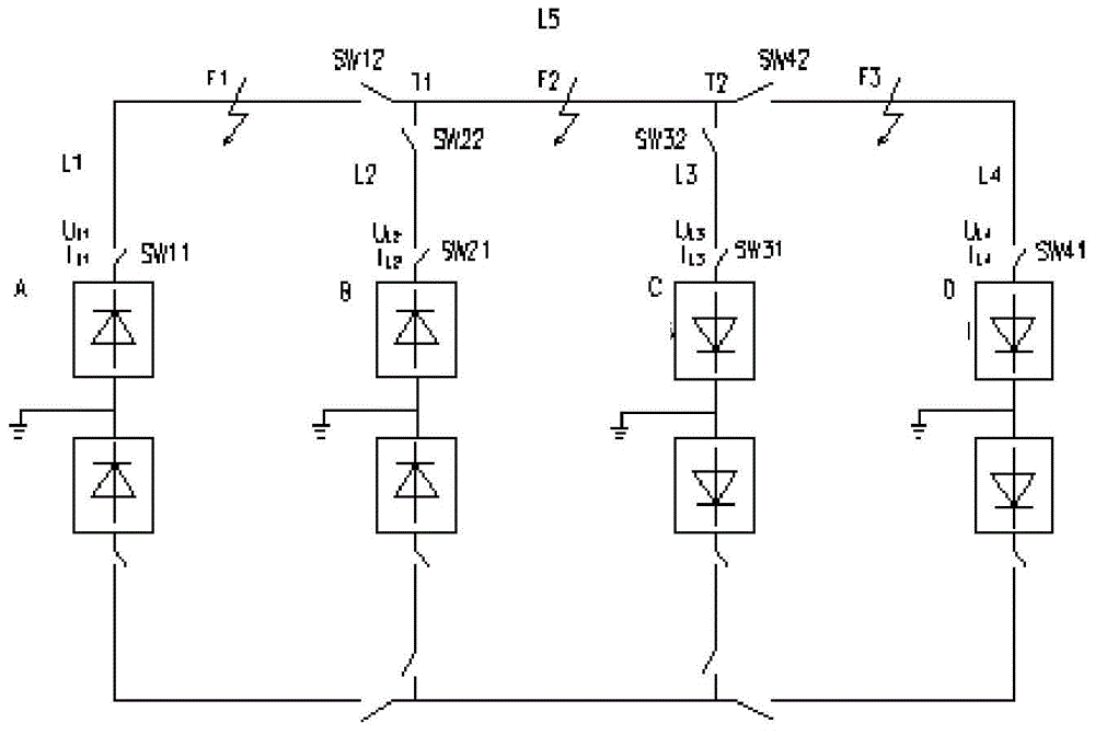
[0030] refer to figure 1 , the multi-terminal DC system model involved in this embodiment is a four-terminal model including converter stations A, B, C, and D, wherein converter station A and converter station B are rectifier stations, and converter station C and converter station D are It is an inverter station; in this four-terminal model, two multi-terminal DC line T junctions T1 and T2 are formed, and a switch station is set at the T junction or combined with the corresponding converter station to set up a switching station; T1 and T2 are used as fulcrums to form AT1 and BT1 , CT2 and DT2 four DC branches, set the length of each branch as L1, L2, L3 and L4 respectively, and the distance between T1 and T2 is L5; An AC circuit breaker or a fast DC switch is set at the flow station to form the breaking devices SW11, SW12, SW21, SW22, SW31, SW32, SW41, SW42 of the multi-terminal DC line.

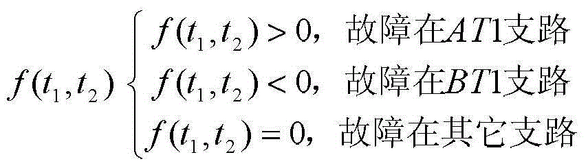
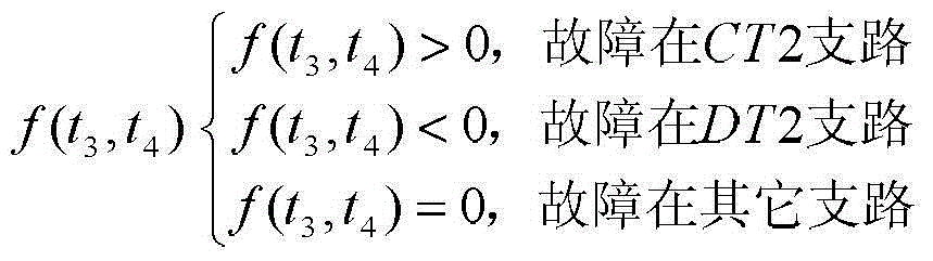
[0031] The method for discriminating the fault branch of the multi-terminal DC line pro...


PUM


Abstract

The invention relates to a fault branch identification method and apparatus for multi-terminal DC line protection. The method is characterized by comprising the following steps: arranging a multi-terminal DC system model, forming T connection points of multi-terminal DC lines, arranging switching stations at the T connection points or combining with corresponding converter stations and arranging the switching stations, and forming a plurality of multi-terminal DC branches by taking the T connection points as fulcrums; arranging AC circuit breakers or fast DC switches in the switching stations; and arranging a reference synchronous clock, and the reference synchronous clock selecting a GPS or a Beidou for synchronous time setting; detecting fault raveling waves received by each converter station, by taking the time differences of the fault raveling waves received by the converter stations, constructing a characteristic function, calculating the characteristic values of the function, comparing the characteristic values with zero, and determining the generation branches of the fault traveling waves. According to the invention, the time differences of the fault raveling waves are received through the converter stations, and the transmission distance relations of the fault raveling waves are calculated for determining the generation branches of faults, such that the line structure is simplified, the faults can be determined and handled through calculation, and the action speed is rapid.

Description

technical field [0001] The invention relates to a method and device for judging a fault branch of multi-terminal DC line protection, belonging to the technical field of fault analysis and judgment in power systems. Background technique [0002] Multi-terminal DC transmission has the characteristics of multi-source power supply, multi-drop point power reception, and single line failure does not affect other normal systems. The multi-terminal DC transmission system has obvious advantages when multiple AC systems require DC interconnection, multi-power supply and multi-drop power receiving requirements, and land acquisition conditions cannot meet the expansion of the original double-terminal system. Multi-terminal DC transmission has played an important role in my country's "West to East Power Transmission" strategy. In recent years, both State Grid and China Southern Power Grid have put into construction and commercial operation several DC transmission projects. [0003] In ...

Claims


Application Information

Patent Timeline
Patent Type & Authority Applications(China)
IPC IPC(8): H02H7/26H02J3/36G01R31/08
CPCY02E60/60
Inventor 施世鸿贾红舟伦振坚谷新梅谭茂强冯晓东
Owner CHINA ENERGY ENG GRP GUANGDONG ELECTRIC POWER DESIGN INST CO LTD
Why Eureka
Try Eureka