Surface-coated cutting tool

A cutting tool and coating technology, which is applied in the direction of manufacturing tools, workpieces, drilling accessories, etc., to achieve the effects of excellent defect resistance, excellent peeling resistance, and extended service life

Active Publication Date: 2014-05-28
TUNGALOY CORP
View PDF8 Cites 3 Cited by
  • Summary
  • Abstract
  • Description
  • Claims
  • Application Information

AI Technical Summary

Problems solved by technology

However, higher chipping resistance is required depending on the application or usage conditions of the tool

Method used


Image

  • Surface-coated cutting tool
  • Surface-coated cutting tool
  • Surface-coated cutting tool

Examples


Embodiment

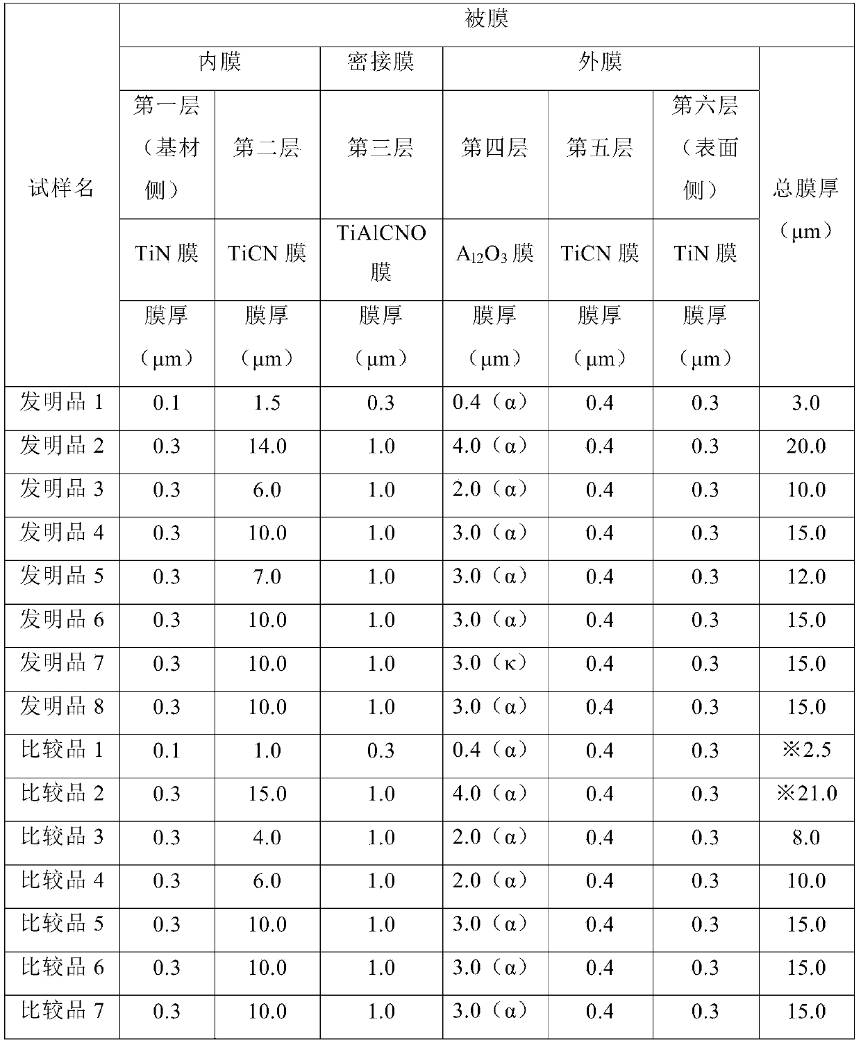
[0063] Sintered WC powder with an average particle size of 4.5 μm: 89% by weight, TiCN powder with an average particle size of 1.5 μm: 2% by weight, (Ta, Nb) C powder with an average particle size of 1.5 μm: 2% by weight, an average particle size of 1.5 μm Co powder: 7% by weight mixed powder to obtain a WC-(Ti, W, Ta, Nb) (C, N)-Co-based WC-based cemented carbide. This WC-based cemented carbide was processed into an insert in the shape of ISO standard CNMG120412, and this was used as a base material. In addition, a beta-depleted layer consisting only of WC and Co was formed near the surface of the WC-based cemented carbide substrate. The thickness of the de-beta layer in the flank was 15 μm. A film having the film composition shown in Table 1 was formed on the surface of the WC-based cemented carbide substrate by chemical vapor deposition. In addition, the 4th layer of Table 1 (Al 2 o 3 film) in (α) means α-type Al 2 o 3 Membrane, (κ) indicates κ-type Al 2 o 3 membran...


PUM

PropertyMeasurementUnit
thicknessaaaaaaaaaa
Vickers hardnessaaaaaaaaaa
thicknessaaaaaaaaaa

Abstract

The present invention provides a surface-coated cutting tool having excellent defect resistance, and relates to a surface-coated cutting tool characterized in comprising: a base material of WC-based cemented carbide and a coating formed by chemical vapor deposition on the surface of the base material; a cutting face, a flank face, and a cutting-blade ridgeline part disposed between the cutting face and the flank face being provided; the total film thickness of the entire coating having an average value of 3-20 [mu]m; and at least one diagonal crack having an advance angle of 45 DEG or less in relation to the surface of the coating being present on the cutting surface within 300 [mu]m of the cutting blade ridgeline part.

Description

technical field [0001] The present invention relates to a coated cutting tool having excellent chipping resistance, and more particularly to a coated cutting tool which exhibits excellent chipping resistance when used in heavy cutting such as steel or cast iron, and which can be used even in milling or cutting of steel or cast iron or the like. A coated cutting tool that exhibits excellent chipping resistance even during interrupted cutting. Background technique [0002] It is well known that a coated cutting tool is formed by vapor-depositing a film with a total film thickness of 3 to 20 μm on the surface of a tungsten carbide-based cemented carbide (hereinafter referred to as WC-based cemented carbide) substrate by chemical vapor deposition. It can be used for cutting steel, etc., where the coating is composed of a single layer of Ti carbide, nitride, carbonitride, carbon oxide, carbonitride, and aluminum oxide, or two or more multilayer films. composed of layers. [000...

Claims


Application Information

Patent Timeline
Patent Type & Authority Applications(China)
IPC IPC(8): B23B27/14B23C5/16C23C16/34C23C16/36C23C16/40
CPCC23C30/00C23C30/005C23C16/34C23C16/36C23C16/403C23C16/56Y10T407/24B23C5/16B23B27/14B23B2224/00B23B2228/10B23C2224/00B23C2228/10
Inventor 平野雄亮
Owner TUNGALOY CORP
Why Eureka
Try Eureka