Ultralow-temperature fuel gas temperature protection method for LNG (liquefied natural gas) engine

A gas temperature and engine technology, applied in engine components, engine control, machine/engine, etc., can solve problems such as low gas temperature, component failure, poor LNG gasification, etc.

Active Publication Date: 2014-06-04
WEICHAI XIGANG NEW ENERGY POWER
View PDF6 Cites 3 Cited by
  • Summary
  • Abstract
  • Description
  • Claims
  • Application Information

AI Technical Summary

Problems solved by technology

[0004] During the use of LNG, gasification will be poor, and the gas temperature will be too low. If the gas temperature is too low, it will affect the safety of the vehicle.
Because the operating temperature range of key components on gas pipelines such as solenoid valves, voltage regulators, and gas nozzles is generally between -40°C and 120°C, too low gas temperature will cause these components to fail and damage the seal. The structure leaks, or the circulating water in the carburetor freezes and expands, causing the carburetor to rupture. Leakage of low-temperature LNG may cause low-temperature injury to personnel. In addition, because LNG leaks into the atmosphere, it will quickly volatilize and spread to fill the entire engine compartment. If it is ignited by the high-temperature components on the engine or the ignition system leaks electricity, the consequences are very serious. The LNG natural gas engine currently in use does not have a reliable ultra-low temperature gas temperature protection function

Method used


Image

  • Ultralow-temperature fuel gas temperature protection method for LNG (liquefied natural gas) engine
  • Ultralow-temperature fuel gas temperature protection method for LNG (liquefied natural gas) engine
  • Ultralow-temperature fuel gas temperature protection method for LNG (liquefied natural gas) engine

Examples


Embodiment Construction

[0058] Below in conjunction with accompanying drawing and embodiment, further elaborate the present invention. In the following detailed description, certain exemplary embodiments of the invention are described by way of illustration only. Needless to say, those skilled in the art would realize that the described embodiments can be modified in various different ways, all without departing from the spirit and scope of the present invention. Accordingly, the drawings and description are illustrative in nature and not intended to limit the scope of the claims.

[0059] See figure 1 , figure 2 , image 3 , Figure 4 and Figure 5 .

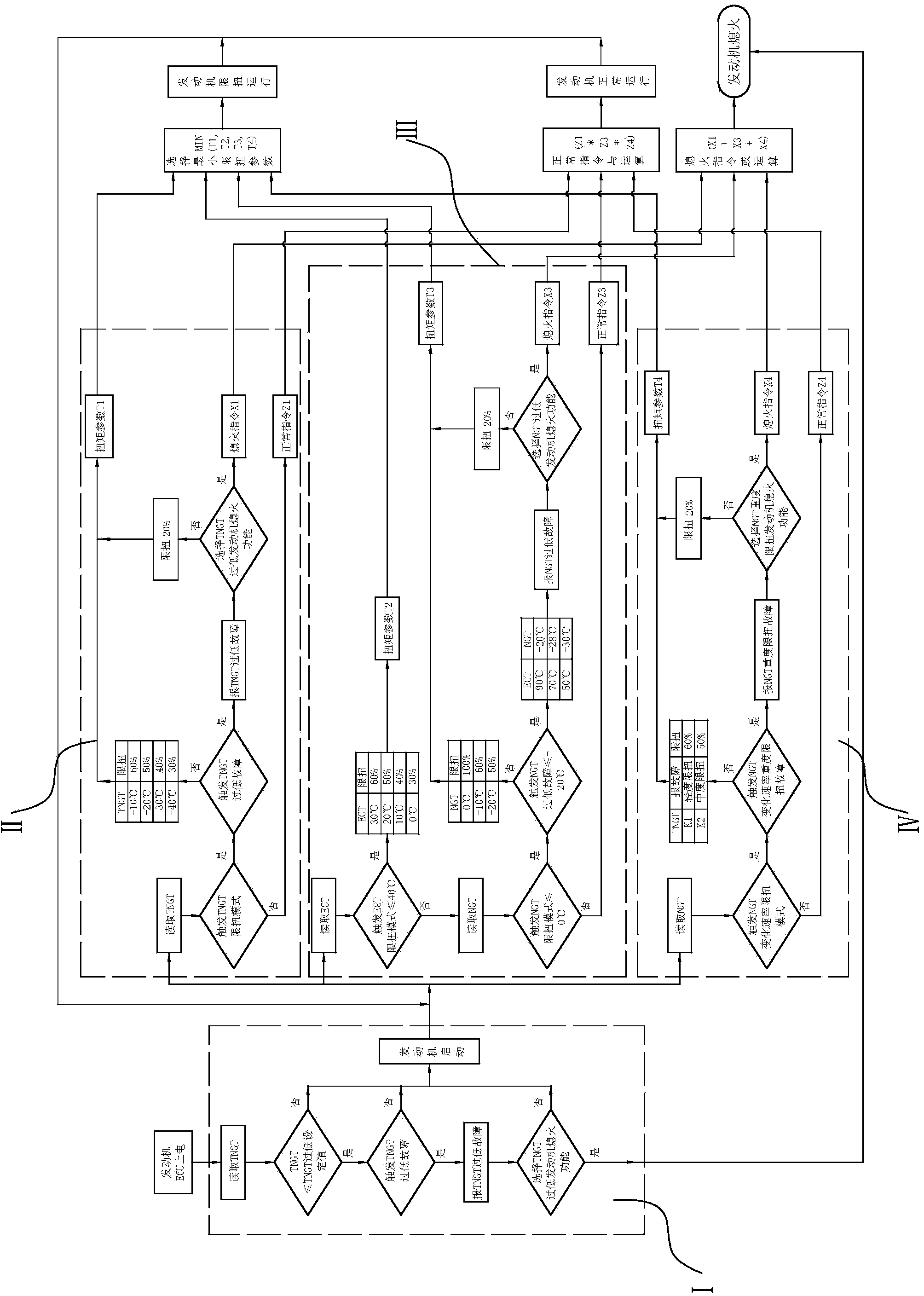
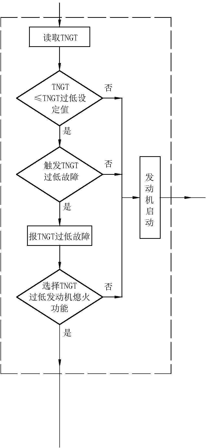
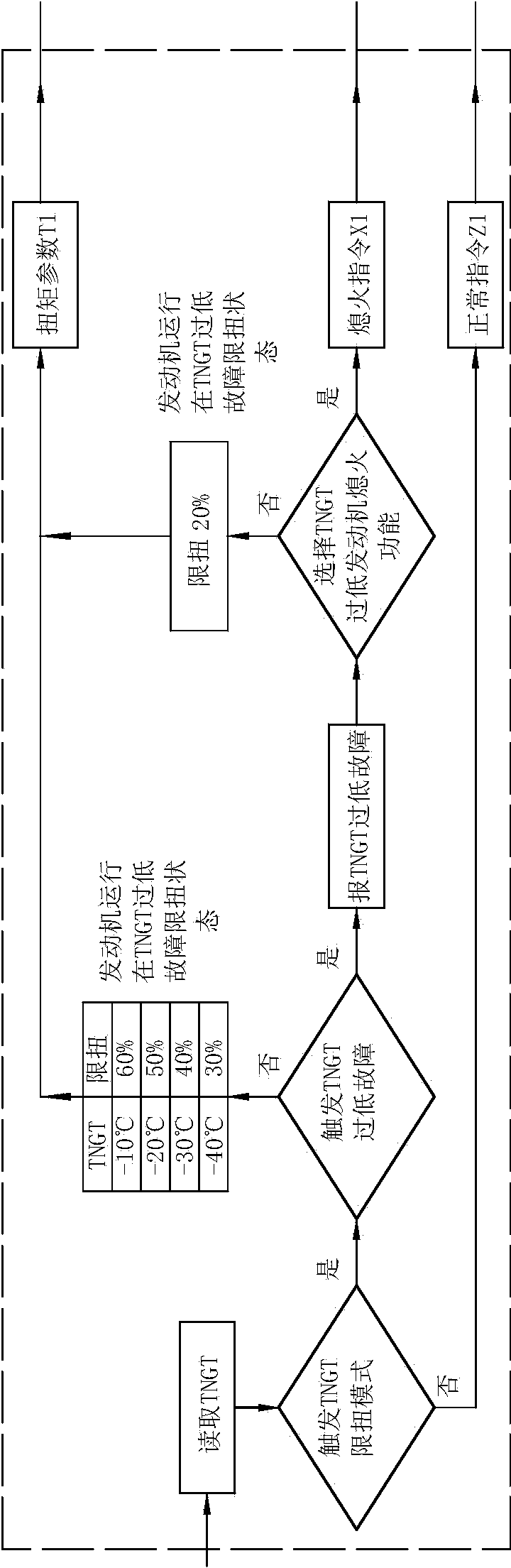
[0060] A method for protecting the ultra-low temperature gas temperature of an LNG engine, comprising the following steps

[0061] The first step is to install temperature sensors at the outlet of the carburetor, the inlet of the gas metering valve, and the water outlet of the engine in advance, and respectively collect the outlet temperature...


PUM


Abstract

The invention discloses an ultralow-temperature fuel gas temperature protection method for an LNG (liquefied natural gas) engine. The method includes the following steps: step 1, mounting temperature sensors at an outlet of a vaporizer, an inlet of a fuel gas metering valve and a water outlet of the engine in advance respectively, correspondingly collecting temperature TNGT of the outlet of the vaporizer, temperature NGT of the inlet of the fuel gas metering valve and temperature ECT of the water outlet of the engine respectively, and presetting TNGT control parameters, NGT control parameters and ECT control parameters respectively; step 2, after an engine ECU (electronic control unit) is power-on, performing engine start protection through judgment on the TNGT; step 3, reading the TNGT, the NGT and the ECT, and through logical operation, judging to perform torsion-limited engine operation, normal engine operation or engine stall; step 4, if the torsion-limited engine operation or the normal engine operation is performed in the step 3, repeating the step 3. By the ultralow-temperature fuel gas temperature protection method, reliable low-temperature protection to a fuel gas supply system of the LNG engine is realized, so that personal injuries and economic losses both caused by low temperature during use of the LNG engine are avoided.

Description

technical field [0001] The invention relates to the technical field of LNG engine electronic control, in particular to a method for protecting the temperature of ultra-low temperature gas of an LNG engine. Background technique [0002] The fuel for LNG (liquefied natural gas) engines is stored in LNG tanks at ultra-low temperatures, and the temperature ranges from -123°C to -162°C depending on the saturation pressure. [0003] After LNG flows out of the gas cylinder, it first needs to be heated and vaporized by the vaporizer to become gaseous natural gas with a suitable temperature, and then passes through the solenoid valve, voltage regulator, gas filter, heat exchanger on the engine and gas thermostat, and then passes through the gas metering valve. Entering the engine, the heat source required for the vaporization process comes from the engine circulating water. [0004] During the use of LNG, gasification will be poor, and the gas temperature will be too low. If the gas...

Claims


Application Information

Patent Timeline
Patent Type & Authority Applications(China)
IPC IPC(8): F02D45/00F02N15/10
Inventor 邵思东周伟伟
Owner WEICHAI XIGANG NEW ENERGY POWER
Why Eureka
Try Eureka