Electrostatic transducer

An electrostatic, transducer technology used in the loudspeaker field

Active Publication Date: 2014-06-04
WARWICK AUDIO TECH LTD
View PDF8 Cites 2 Cited by
  • Summary
  • Abstract
  • Description
  • Claims
  • Application Information

AI Technical Summary

Problems solved by technology

[0006] A problem with this type of electrostatic loudspeaker is obtaining sufficient displacement of the membrane

Method used


Image

  • Electrostatic transducer
  • Electrostatic transducer
  • Electrostatic transducer

Examples


Embodiment Construction

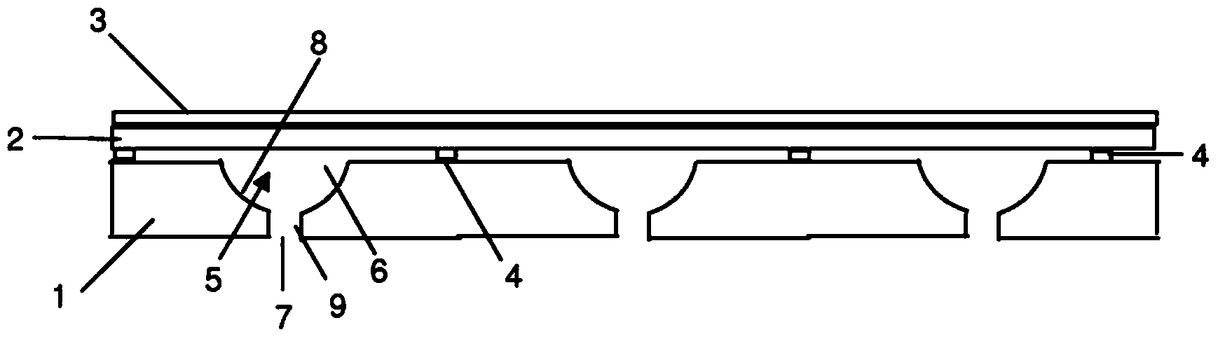
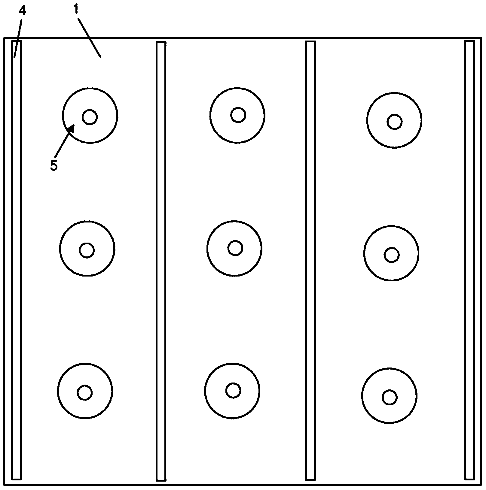
[0059] Such as figure 1 The loudspeaker shown comprises a first layer or backplane 1 having a thickness of approximately 3 mm. This backplane is made of an insulating polymer, on the upper surface of which is provided a conductive layer (not shown). On this conductive layer is a flexible layer 2 of insulating polymer film, on which is a conductive layer 3 . The conductive layer 3 and the insulating layer 2 may be separate layers, but in this embodiment the conductive layer 3 is in the form of metallization on the outer surface of the insulating layer 2 to provide a film with a total thickness of about 12 microns (microns), Although films with a thickness of about 6 microns may be used in some embodiments. Mylar TM The insulating tape 4 is placed between layer 1 and layer 2. The bands are between 1 and 2 mm wide and approximately 20 to 25 microns thick.

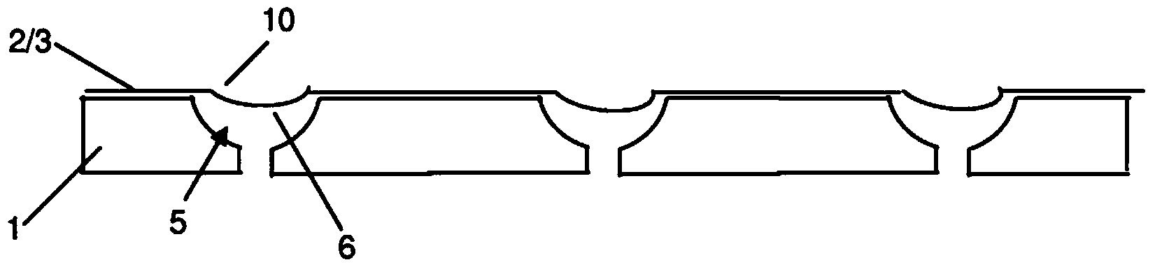
[0060] The back plate 1 is provided with rows of through holes 5 . Each aperture 5 has an inlet 6 facing the insulatin...


PUM


Abstract

An electrostatic transducer comprises an electrically conductive first layer (1), a flexible insulating second layer (25) disposed over the first layer, and a flexible electrically conductive third layer (26) disposed over the second layer. Between the first and the second layers are provided spacers (24) and between the second and the third layers are provided spacers (27). The spacers may be provided by strips of adhesive or by bonding the layers together by welding, for example. The first layer (1) is provided with an array of through apertures (5) each having an inlet (6) facing the second layer (2) and an outlet (7). In response to signals applied to the first and third layers, the second and third layers have portions which are displaced towards the outlets of the apertures by electrostatic forces. The apertures (5) may have conducting walls and the walls may converge.

Description

technical field [0001] The present invention relates to an electrostatic transducer and in particular but not exclusively to loudspeakers suitable for reproducing audio signals. Background technique [0002] Conventional electrostatic speakers include a conductive film disposed between two porous conductive back plates to form a capacitor. A DC bias is applied to the membrane, while an AC signal voltage is applied to the two backplates. Hundreds or even thousands of volts may be required. The signal results in a force on the charged membrane, which moves, driving the air on either side of it. [0003] In US7095864 an electrostatic loudspeaker comprising a multilayer board is disclosed. An electrically insulating layer is sandwiched between two conductive outer layers. The insulating layer has a circular depression on one side thereof. When a DC bias is applied to the two conductive layers, parts of one of them are attracted to the insulating layer forming a snare head s...

Claims


Application Information

Patent Timeline
Patent Type & Authority Applications(China)
IPC IPC(8): H04R19/02H04R7/08
CPCH04R19/02H04R7/08H04R19/04H04R23/006H04R2201/003
Inventor 布莱恩·阿特金斯邓肯·比尔森大卫·霍尔
Owner WARWICK AUDIO TECH LTD
Why Eureka
Try Eureka