
Multi-beam shaping laser processing system

A laser processing, multi-beam technology, used in laser welding equipment, metal processing equipment, optics, etc., can solve the problems of difficult to meet the needs of high-precision processing, expensive lasers, reducing the energy of a single beam, etc., to improve processing efficiency, The effect of improving the effect of laser processing

Inactive Publication Date: 2014-06-11
SUZHOU ORCHID OPTOELECTRONICS TECH
View PDF7 Cites 14 Cited by
  • Summary
  • Abstract
  • Description
  • Claims
  • Application Information

AI Technical Summary

Problems solved by technology

[0002] The market's requirements for the quality of laser-cut chips are getting higher and higher, mainly reflected in the need for smaller heat-affected zones, faster cutting speeds, etc. In order to achieve these requirements, picoseconds, femtoseconds or even shorter pulse widths have appeared. Attosecond lasers mainly improve the cutting effect by changing the pulse width, but most of these lasers are expensive. At present, most of the laser equipment used for fine processing on the market uses nanosecond ultraviolet lasers, and the price is much lower than the above-mentioned ones. High-end lasers, but due to the limitations of the optical structure, it is becoming more and more difficult to meet the needs of high-precision processing. To achieve fine processing, one must either replace the laser or improve the optical structure, and the cost of improving the optical structure is relatively small;
[0003] Using laser to process samples is the most common process in the field of laser processing. When the traditional laser processing system needs to increase the laser cutting width or deepen the cutting depth, it often uses processes such as increasing laser power, defocus processing or multiple scribing. Although these methods can increase the cutting width or cutting depth, they will bring problems such as increasing the heat-affected zone, poor cutting line shape and low efficiency;
[0004] Equipment or articles using diffractive optical elements to improve processing efficiency have appeared, but this method only divides one beam of laser into multiple beams, reduces the energy of a single beam, and improves the cutting effect through multi-beam trailing cutting. Focus on the energy distribution of the laser spot, and the energy distribution of the laser will affect the cutting effect to a certain extent;
[0005] Another existing beam shaping process is to achieve beam shaping through cylindrical lens groups. Equipment and articles that obtain strip-shaped focusing spots with a large aspect ratio have also appeared. The starting point of this method is mainly to reduce the focusing spot. The power density in the direction of the long axis is used to reduce the heat-affected zone, but since there is only one laser spot, considering the relationship between the power density and the material damage threshold, the energy at both ends of the laser spot in the long axis direction is mainly for the material. heating, no removal effect;

Method used


Image

  • Multi-beam shaping laser processing system
  • Multi-beam shaping laser processing system
  • Multi-beam shaping laser processing system

Examples


Embodiment

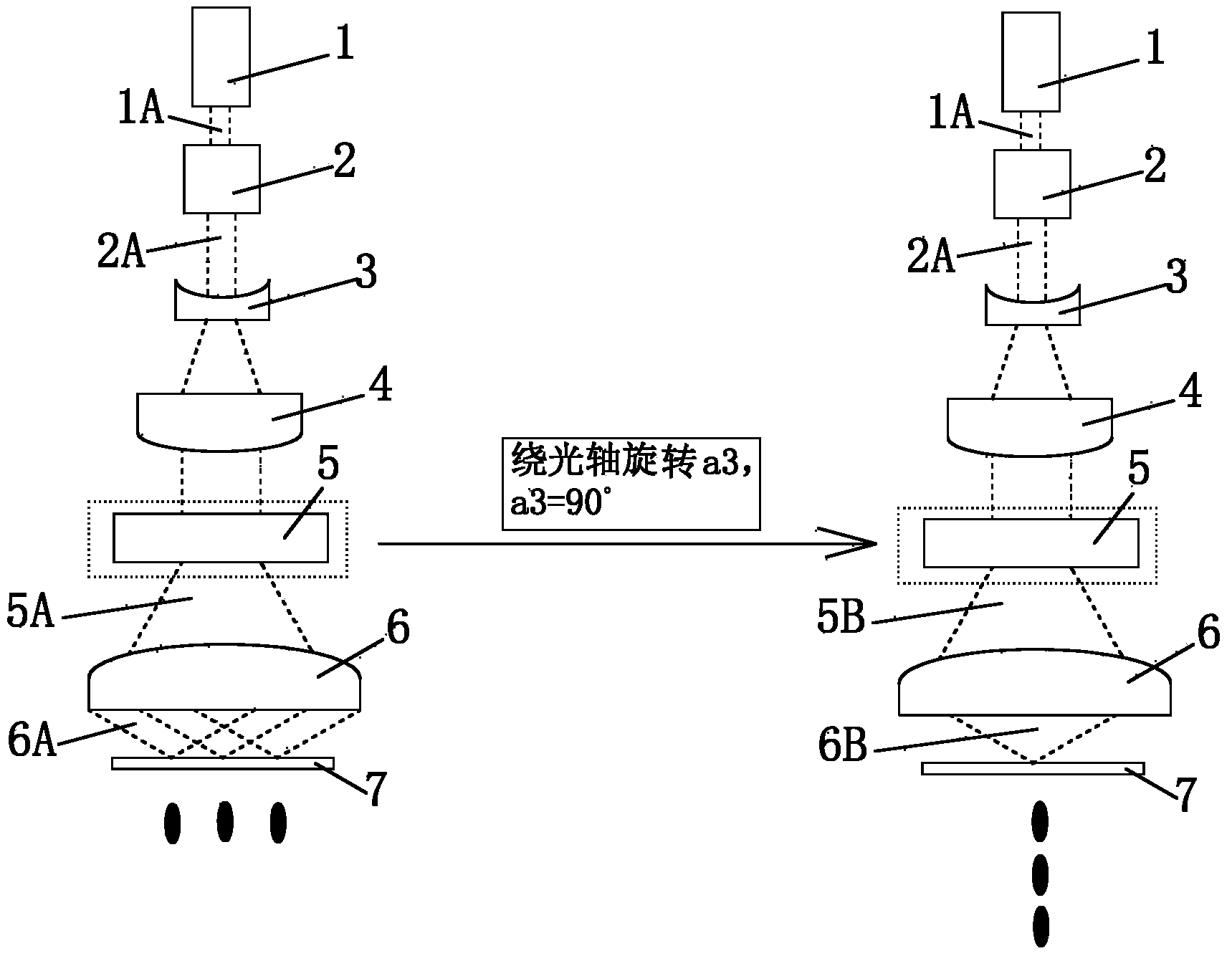
[0038] Example: Figure 3 to Figure 6 A specific embodiment of such a multi-beam shaping laser processing system of the present invention is shown. like image 3As shown, the multi-beam shaping laser processing system includes a laser 1 , a beam expander 2 , a cylindrical concave lens 3 , a cylindrical convex lens 4 , a one-dimensional diffractive optical element 5 and a focusing lens 6 arranged in sequence along the direction of the laser light path. The function of the beam expander 2 is mainly to change the diameter of the beam. Of course, the divergence angle of the laser beam expanded by the beam expander will also be reduced, but the laser divergence angle of most lasers has been controlled to be relatively small at present. If the diameter of the original laser beam emitted by the laser 1 is large enough (greater than 5mm), then the beam expander 2 does not need to be provided. The beam expansion magnification of the beam expander 2 is generally selected between 1 and...


PUM


Abstract

The invention discloses a multi-beam shaping laser processing system which comprises a laser, a cylindrical concave lens, a cylindrical convex lens, a one-dimensional diffraction optical element and a focusing lens which are sequentially arranged along the direction of a light path of laser. According to the multi-beam shaping laser processing system disclosed by the invention, a processing effect of common ultraviolet nanosecond laser processing equipment can be improved, and processing efficiency is improved.

Description

technical field [0001] The invention relates to a multi-beam shaping laser processing system, which is mainly used for grooving or cutting processing of chips. Background technique [0002] The market has higher and higher requirements for the quality of laser cutting chips, which are mainly reflected in the need for a smaller heat-affected zone, faster cutting speed, etc. In order to achieve these requirements, there are picosecond, femtosecond and even shorter pulse widths. Attosecond lasers mainly improve the cutting effect by changing the pulse width, but most of these lasers are expensive. At present, most of the laser equipment used for fine processing on the market use nanosecond ultraviolet lasers, and the price is much lower than the above mentioned ones. High-end lasers, but due to the limitation of optical structure, it is more and more difficult to meet the needs of high-precision processing. To achieve fine processing, either replace the laser or improve the opt...

Claims


Application Information

Patent Timeline
IPC IPC(8): B23K26/073B23K26/067G02B27/09
CPCB23K26/364B23K26/064B23K26/0648B23K26/0676B23K26/0736B23K26/38
Inventor 王杰潘传鹏
Owner SUZHOU ORCHID OPTOELECTRONICS TECH
Learn More