Drive device for fan-shaped paddle type drying machine

A driving device and dryer technology, which is used in dewatering/drying/concentrating sludge treatment, mixers with rotary stirring devices, mixers, etc., can solve problems such as land occupation and environmental pollution, and achieve small footprint, Easy to use, not easy to stick

Inactive Publication Date: 2014-06-11
XIAN ALL SAFE SCI & TECH
View PDF0 Cites 0 Cited by
  • Summary
  • Abstract
  • Description
  • Claims
  • Application Information

AI Technical Summary

Problems solved by technology

Such treatment not only pollutes the environment but also takes up a lot of land.

Method used


Image

  • Drive device for fan-shaped paddle type drying machine
  • Drive device for fan-shaped paddle type drying machine

Examples


Embodiment 1

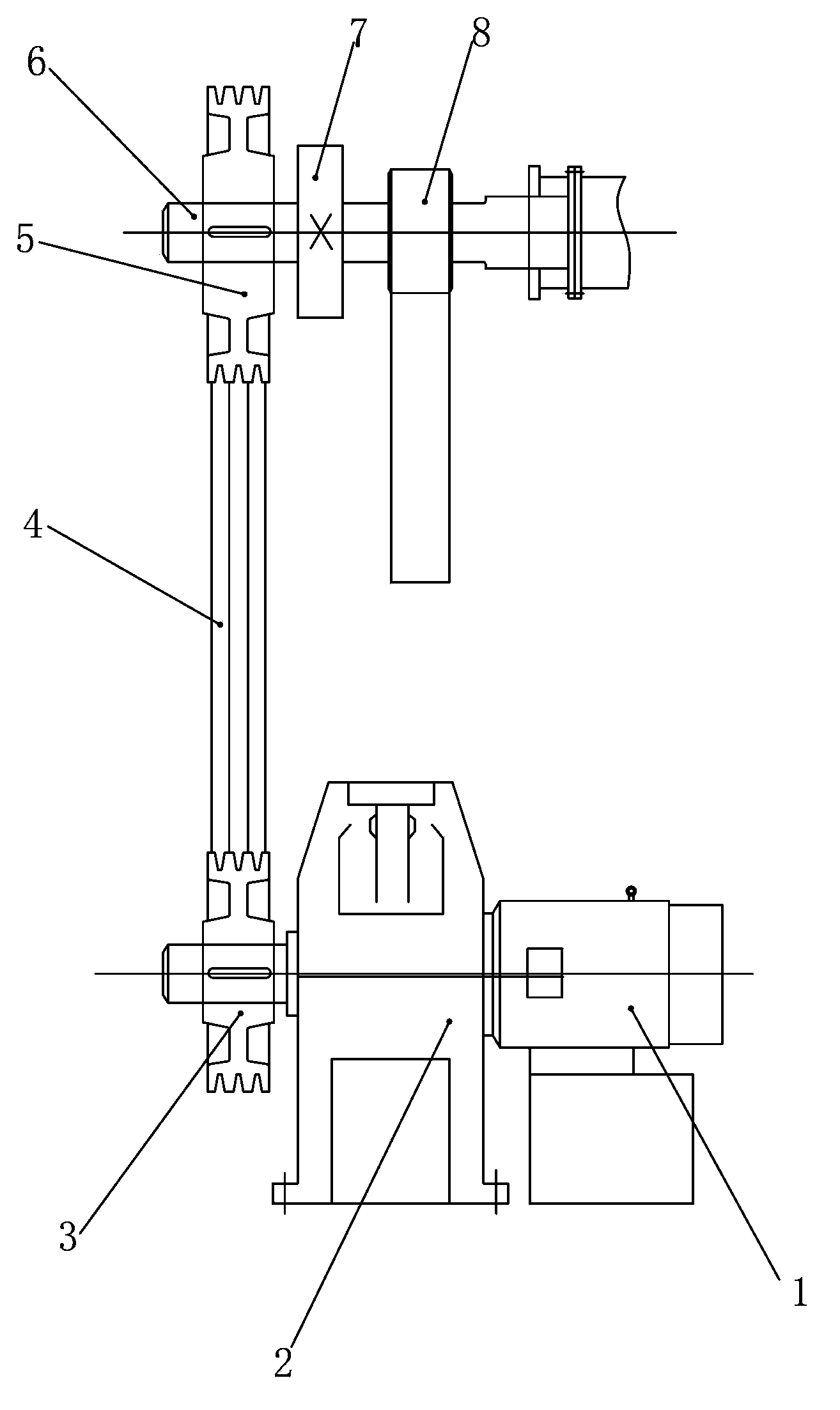
[0022] Such as figure 1 The driving device for a fan-shaped paddle dryer includes a power unit, a paddle shaft 6, a paddle shaft 2, a bearing box 8 and a bearing box 2, and the power unit includes a motor 1 and a reducer 2 , the output shaft of the motor 1 is connected with the input shaft of the reducer 2, and the output shaft of the reducer 2 is connected with a transmission device for driving the rotation of the paddle shaft one 6 and the paddle shaft two, and the paddle Shaft 2 is arranged in parallel on one side of paddle shaft one 6. A plurality of fan-shaped paddles are arranged on said paddle shaft one 6 and paddle shaft two. Said paddle shaft one 6 passes through bearing one and bearing box one. 8 is rotationally connected, and the paddle shaft 2 is rotationally connected with the bearing housing 2 through the bearing 2.

[0023] In this embodiment, the transmission device includes a small pulley 3 mounted on the output shaft of the reducer 2, a large pulley 5 mounte...

Embodiment 2

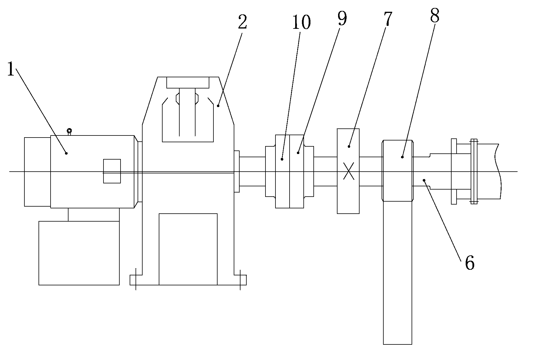
[0027] Such as figure 2 As shown, the difference between this embodiment and Embodiment 2 is that the transmission device includes a left coupling 10 installed on the output shaft of the reducer 2 and a right coupling installed at one end of the blade shaft 6 9. The left coupling 10 is connected with the right coupling 9, the first paddle shaft 6 is equipped with a driving gear 7, and the paddle shaft 2 is provided with a driven gear that meshes with the driving gear 7 gear.

[0028] During use, the motor 1 drives the reducer 2, and the output shaft of the reducer 2 drives the paddle shaft one 6 to rotate through the left coupling 10 and the right coupling 9, and the driving gear 7 on the paddle shaft one 6 is connected to the blade The driven gears on the second shaft are meshed, thereby driving the second paddle shaft and the first paddle shaft 6 to rotate together. The utility model has the advantages of simple structure and convenient use.


PUM


Abstract

The invention discloses a drive device for a fan-shaped paddle type drying machine. The drive device comprises a power device, a first paddle shaft, a second paddle shaft, a first bearing box and a second bearing box, wherein the power device comprises a motor and a speed reducer; an output shaft of the motor is connected with an input shaft of the speed reducer; an output shaft of the speed reducer is connected with a transmission device for driving the first and second paddle shafts to rotate; the second paddle shaft is arranged in parallel on one side of the first paddle shaft; a plurality of fan-shaped paddles are arranged on both the first paddle shaft and the second paddle shaft; the first paddle shaft is in rotary connection with the first bearing box through a first bearing; the second paddle shaft is in rotary connection with the second bearing box through a second bearing. The drive device for the fan-shaped paddle type drying machine is stable in running, reasonable in structure and small in floor area to save space, and can be used for effectively stirring and turning sludge in a shell to ensure that the sludge can not stick together and agglomerate.

Description

technical field [0001] The invention relates to a driving device, in particular to a driving device for a fan-shaped paddle dryer. Background technique [0002] With the acceleration of my country's urbanization process and the strengthening of urban infrastructure, the rate of urban sewage treatment has gradually increased, resulting in a large amount of municipal sludge. If these sludges are not treated in a timely, effective and stable manner, they will become a great hidden danger to the regional environment and people's life safety in our country. In addition, industrial production processes such as papermaking, chemical industry, tanning, printing and dyeing, and dredging of rivers and lakes will also produce a large amount of sludge. The harmless treatment of sludge has become a major environmental protection problem that must be solved in the process of urban scientific development. At present, the method usually adopted by sewage treatment plants is to dehydrate t...

Claims


Application Information

Patent Timeline
Patent Type & Authority Applications(China)
IPC IPC(8): C02F11/12B01F15/00B01F7/04
Inventor 李卫红
Owner XIAN ALL SAFE SCI & TECH
Why Eureka
Try Eureka