
A pressure cut-off device controlled by a solenoid valve

A technology of cut-off device and solenoid valve, applied in the direction of fluid pressure actuating device, safety device, fluid pressure actuating system components, etc. Small, overall size reduction, simple structure effect

Active Publication Date: 2016-03-02
DONGFANG ELECTRIC AUTOMATIC CONTROL ENG CO LTD +1
View PDF5 Cites 0 Cited by
  • Summary
  • Abstract
  • Description
  • Claims
  • Application Information

AI Technical Summary

Problems solved by technology

[0003] In view of the above-mentioned prior art, the technical problem to be solved by the present invention is: the existing pressure cut-off device has large impact force, high noise, serious pressure loss and lack of external indication and alarm functions

Method used


Image

  • A pressure cut-off device controlled by a solenoid valve

Examples


Embodiment Construction

[0024] The present invention will be further described below in conjunction with the accompanying drawings and specific embodiments.

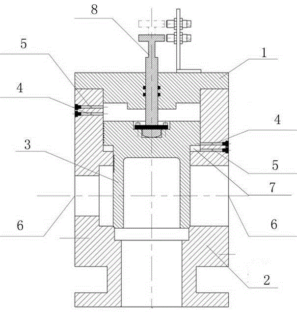
[0025] A pressure cut-off device whose opening and closing is controlled by a solenoid valve, including a housing, a piston, a cover plate, and a solenoid valve; The cover plate is used to control the on and off of the hydraulic oil; the piston is assembled in the housing to divide the housing into a pressure oil chamber, an oil outlet chamber, an oil return chamber and a control oil chamber. There are control oil port and buffer oil port on the housing, the control oil port on the control oil chamber housing is located above the buffer oil port, the control oil port on the oil return chamber housing is located below the buffer oil port, the control oil There are throttle holes in both the control oil port and the buffer oil port, and the diameter of the throttle hole in the control oil port is larger than the diameter of the throttle hole in t...


PUM


Abstract

The invention discloses a pressure stop device with the opening and closing controlled by an electromagnetic valve. The pressure stop device comprises a housing, a piston, a cover plate and the electromagnetic valve. The cover plate is arranged at the top opening of the housing and used for sealing the housing; the electromagnetic valve is mounted on the housing or the cover plate and used for controlling on and off of hydraulic oil; the piston is mounted inside the housing and divides the housing into a pressure oil cavity, an oil outlet cavity, an oil return cavity and a control oil cavity; the housings of the control oil cavity and the oil return cavity are respectively provided with a control oil port and a buffer oil port, the control oil port of the housing of the control oil cavity is arranged above the corresponding buffer oil port, the control oil port of the housing of the oil return cavity is arranged under the corresponding buffer oil port, the insides of the control oil ports and the buffer oil ports are provided with throttle holes, and the diameter of the throttle holes inside the control oil ports is larger than that of the throttle holes inside the buffer oil ports. The pressure stop device with the opening and closing controlled by the electromagnetic valve has the advantages of no impact, no noise, low pressure losses, compact integral size, external indicating and alarming and the like and is applicable to a speed regulating system.

Description

technical field [0001] The invention relates to the technical field of a speed regulating system of a hydroelectric generator, in particular to a pressure cut-off device. Background technique [0002] The speed control system of the hydro-generator is mainly composed of a governor and an oil pressure device. The oil pressure device is mainly composed of two parts: the oil return tank and the pressure oil tank. The pressure oil tank provides a stable pressure oil source for the speed control system. Medium and large units Usually, a pressure cut-off device is used to realize the on-off function of the pressure oil tank and the hydraulic part of the speed control system. The pressure cut-off device often adopts a cartridge valve to realize the flow of large flow. The cartridge valve is composed of a bush and a piston, and its switch is realized by the pressure difference between the upper and lower chambers of the piston. Since the cartridge valve is composed of two parts, wh...

Claims


Application Information

Patent Timeline
Patent Type & Authority Patents(China)
IPC IPC(8): F15B13/02F15B21/00F03B15/00
CPCY02E10/20
Inventor 贾小平曹维福谭文韬
Owner DONGFANG ELECTRIC AUTOMATIC CONTROL ENG CO LTD
Learn More