Design method of optical probe for measuring laser absorption spectrum

A laser absorption spectroscopy, optical probe technology, applied in the field of embedded optical probes, can solve the problems of serious induced vibration, large differences in components and structures, and difficulty in sealing, so as to enhance the ability to resist induced vibration, reduce mass and size, The effect of reducing the size of the structure

Active Publication Date: 2014-06-11
PLA PEOPLES LIBERATION ARMY OF CHINA STRATEGIC SUPPORT FORCE AEROSPACE ENG UNIV
View PDF7 Cites 6 Cited by
  • Summary
  • Abstract
  • Description
  • Claims
  • Application Information

AI Technical Summary

Problems solved by technology

[0010] 1) The probe is installed on the outside of the wall and is independent of the optical window, resulting in a larger overall size. In the actual flow field of the engine, etc., it is often difficult to install due to space constraints
In addition, because the external optical path of the flow field is long and difficult to close, it is not convenient to purify it
[0011] 2) The probe has a large size and mass and is installed on the outside of the wall, which induces serious vibration when the engine is working, which increases the difficulty of beam capture
At the same time, this probe installation form is vulnerable
For example, in the experiment in Document 2, the connection bolts of the commercial adjustment frame fell off due to vibration.
[0012] 3) The receiving probe adopts the method of focusing mirror and detector. Although it is beneficial to enhance the capturing ability of the beam, the detector requires strict thermal protection measures, and due to the bending of the optical path, it increases the difficulty of installation and is not conducive to reducing the structural size
[0013] 4) Although the design ideas of the three documents are similar, because they are only aimed at specific installation environments, the devices and structures used are quite different, especially for the realization of the speed measurement function, the axial direction of the probe forms a certain angle with the normal direction of the wall, which lacks Versatility

Method used


Image

  • Design method of optical probe for measuring laser absorption spectrum
  • Design method of optical probe for measuring laser absorption spectrum
  • Design method of optical probe for measuring laser absorption spectrum

Examples


Embodiment Construction

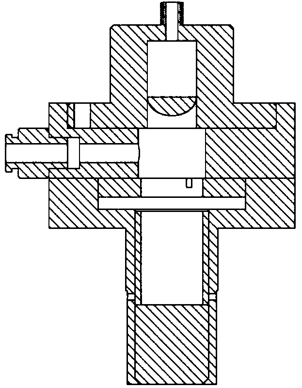
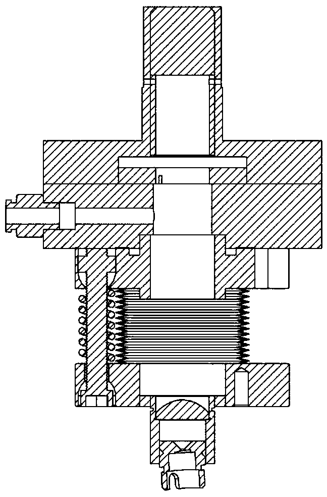
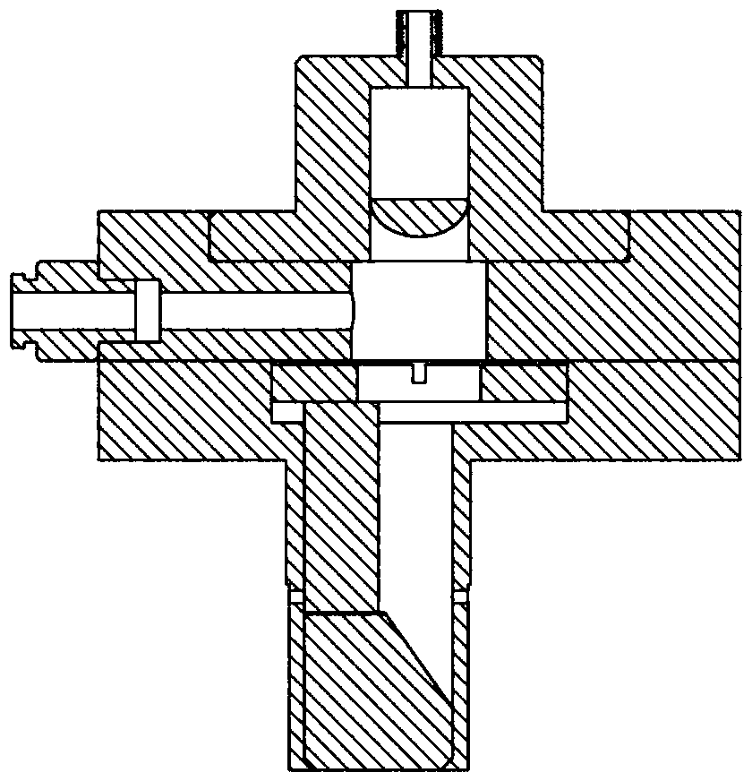
[0029] The optical probe is further described in detail in conjunction with the accompanying drawings. Figure 1-Figure 4 They are schematic diagrams of receiving and transmitting probes used for temperature measurement and speed measurement respectively.

[0030] The optical probe is designed in a modular fashion to allow interchangeability of components as much as possible. Reliable optical alignment in vibration and high-temperature flow field environments is achieved by comprehensively considering the requirements of aerodynamic refraction of the beam direction, adjustment and locking of the emission direction, integration of the optical window and the probe, thermal protection of the sensor, and resistance to vibration and shock. ability.

[0031] In order to reduce the need for thermal protection and make the structure more compact, the receiving probe abandons the structure of focusing mirror and detector, but uses a collimator to focus the beam passing through the flo...


PUM

PropertyMeasurementUnit
lengthaaaaaaaaaa
diameteraaaaaaaaaa
thicknessaaaaaaaaaa

Abstract

The invention provides an embedded type optical probe for measuring a laser absorption spectrum. The embedded type optical probe comprises a transmitting probe and a receiving probe, wherein the transmitting probe comprises a first wall face embedded part, a first transition part, a corrugated pipe structure and a first corrugated pipe; the receiving probe comprises a second wall face embedded part, a second transition part and a second corrugated pipe. Dried nitrogen is fed into an inner cavity of the probe so as to conveniently purify a protection gas film of a window and a free light path outside a convection field. The optical probe has the advantages of compact structure, induction vibration resistance, strong commonality, convenience for realizing purification and air film cooling.

Description

technical field [0001] The invention belongs to the technical field of flow field optical measurement, relates to tunable semiconductor laser absorption spectrum technology, in particular to an embedded optical probe technology for laser absorption spectrum measurement. Background technique [0002] Due to the non-contact characteristics and the selectivity of monitoring components, laser measurement technology has become an important development direction of combustion and propulsion flow field diagnosis technology. Among them, tunable diode laser absorption spectroscopy (TDLAS) technology is relatively mature, and can measure key flow field parameters such as gas temperature, component concentration, velocity, and mass flow rate. The TDLAS-based measurement system has significant advantages such as fast time response, simple data analysis, high signal strength, long-distance transmission of light beams by optical fibers, and relatively low price. [0003] Since the 1990s,...

Claims


Application Information

Patent Timeline
Patent Type & Authority Applications(China)
IPC IPC(8): G01N21/39G01N21/01
Inventor 王广宇洪延姬赵文涛
Owner PLA PEOPLES LIBERATION ARMY OF CHINA STRATEGIC SUPPORT FORCE AEROSPACE ENG UNIV
Why Eureka
Try Eureka