Monitoring method for grouting compaction of pre-stressed pipe based on piezoelectric ceramic

A technology of prestressed pipes and piezoelectric ceramics, applied in measuring devices, material analysis through electromagnetic means, instruments, etc., can solve the problems of low monitoring efficiency, difficulty in judging test results, and influence of test results by shock echo method, and achieve Rapid detection, sensitive response, and easy operation

Active Publication Date: 2014-06-11
CHANGSHA UNIVERSITY OF SCIENCE AND TECHNOLOGY +1
View PDF5 Cites 20 Cited by
  • Summary
  • Abstract
  • Description
  • Claims
  • Application Information

AI Technical Summary

Problems solved by technology

However, due to the shielding interference of metal prestressed pipelines and dense steel bundles and the difficulty in accurate dielectric constants, the application of the ground radar method in the monitoring of the compactness of prestressed pipeline grouting is limited; the monitoring efficiency of the impact echo method is low and the impact echo scanning equipment There are high requirements for the surface smoothness and flatness of the surface to be tested. When the surface condition is bad, it is easy to appear the test point of signal loss, which makes it difficult to judge the test result; and the widely used ultrasonic method also has shortcomings. For example, many interference waves are generated due to the influence of concrete strength grade, type of corrugated pipe, and the coupling between concrete and sensors. The detection results are greatly affected by human factors, and there are high requirements for the technical level of operators. The detection position must be within reach, etc.

Method used


Image

  • Monitoring method for grouting compaction of pre-stressed pipe based on piezoelectric ceramic
  • Monitoring method for grouting compaction of pre-stressed pipe based on piezoelectric ceramic
  • Monitoring method for grouting compaction of pre-stressed pipe based on piezoelectric ceramic

Examples


Embodiment

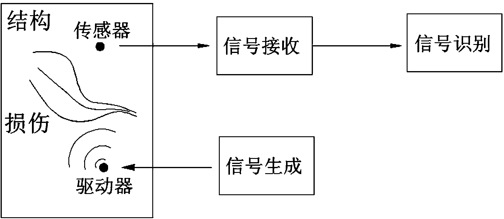
[0043] Such as Figure 4 As shown, a piezoelectric ceramic sheet is pasted on the top and bottom of a prestressed corrugated pipe as a sensor and a driver respectively, and a layer of bisphenol A epoxy resin waterproof layer is coated on the piezoelectric ceramic sheet.

[0044] The sticking position of the piezoelectric ceramic sheet is pre-coated with an insulating layer, and the insulating layer is a uniform epoxy resin insulating layer.

[0045] The specific operation steps of the monitoring method in this example are:

[0046] a. If Figure 4 As shown, seven prestressed steel strands with a nominal diameter of 15.2mm are stretched in a circular prestressed bellows with an inner diameter d of 60mm, an outer diameter D of 73mm, and a nominal wall thickness of 2.5mm, grouting, and natural curing. , Pour C40 concrete after sealing the anchor. Concrete with a length and width of 300×300mm is made as a beam body specimen. The length of the specimen shall be determined accor...


PUM


Abstract

The invention discloses a monitoring method for grouting compaction of a pre-stressed pipe based on piezoelectric ceramic. The monitoring method comprises the following steps: bonding a piezoelectric ceramic sensor at the top of the outer wall of the pre-stressed pipe; bonding a piezoelectric ceramic driver on the corresponding position of the bottom of the outer wall of the pre-stressed pipe; arranging an insulating layer between the outer wall of the pre-stressed pipe and the driver or the sensor; generating a stimulating signal by using any signal function generator; amplifying the stimulating signal by using a high-voltage signal amplifier; stimulating the piezoelectric ceramic driver by using the amplified stimulating signal so as to generate a stress wave in the pre-stressed pipe; taking effects on the piezoelectric ceramic sensor by the stress wave to generate an electric signal; collecting the electric signal generated by the sensor by using a high-frequency signal collection system; and judging the grouting compaction of the pre-stressed pipe by using a wavelet packet energy analyzing method. With the adoption of the method, the uncompacted grouting position can be accurately and rapidly found; the reaction is sensitive, the operation is simple and convenient and the cost is low.

Description

technical field [0001] The invention relates to the field of prestressed concrete structure monitoring, in particular to a method for monitoring the grouting compactness of prestressed pipelines based on piezoelectric ceramic technology. Background technique [0002] The grouting effect of the prestressed concrete structure is very important to ensure the reliability of the prestressed. Whether the bond between the grout and the prestressed pipe is intact directly affects the durability and safety of the prestressed concrete bridge. However, due to the grouting process and some human factors, the grouting of the prestressed pipeline is often not full, so that the prestressed steel bars are not completely wrapped by the slurry, and once the prestressed tendons are corroded, they cannot be found immediately, which may cause sodium chloride, water , A large amount of air enters the pipe, causing fatal quality problems such as corrosion of prestressed tendons, sharp reduction in...

Claims


Application Information

Patent Timeline
Patent Type & Authority Applications(China)
IPC IPC(8): G01N27/00
Inventor 蒋田勇宋钢兵龙伟
Owner CHANGSHA UNIVERSITY OF SCIENCE AND TECHNOLOGY
Why Eureka
Try Eureka