Insulation detection circuit and method thereof
A technology for detecting circuits and insulation states, applied in the directions of testing circuits, measuring electricity, measuring electrical variables, etc., can solve the problems of insulator breakage, leakage, mechanical wear of insulators, etc., and achieve the effect of improving convenience
- Summary
- Abstract
- Description
- Claims
- Application Information
AI Technical Summary
Problems solved by technology
Method used
Image
Examples
Embodiment 1
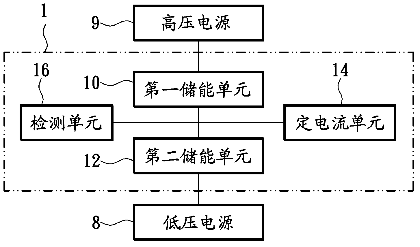
[0073] figure 1 It is a functional block diagram of an insulation detection circuit according to an embodiment of the present invention. see figure 1 . An insulation detection circuit 1 is suitable for detecting the insulation state between a high voltage power source 9 and a low voltage power source 8 of a carrier. The insulation detection circuit 1 is coupled between a carrier and a DC power supply, and the DC power supply is used to supply power to the carrier, or to start a vehicle generator to supply power to the carrier, thereby forming a relatively high-voltage power source 9 and a The low-voltage power supply 8 and the insulation detection circuit 1 include a first energy storage unit 10 , a second energy storage unit 12 , a constant current unit 14 and a detection unit 16 .
[0074] In practical applications, the DC power supply can be realized by a rechargeable battery, and the low-voltage power supply 8 can be realized by grounding the shell of the vehicle or by ...
Embodiment 2
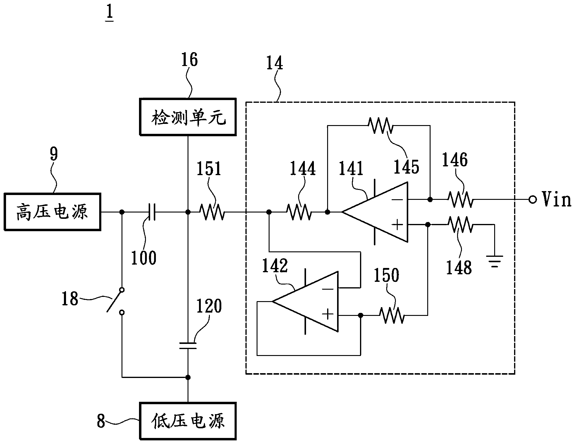
[0093] the above figure 1 The circuit architecture of the middle constant current unit 14 can be implemented with different circuits. Of course, the constant current unit 14 can provide a stable constant current to the second energy storage unit 12 so that the detection unit 16 can detect the insulation state between the high voltage power source 9 and the low voltage power source 8 .
[0094] Figure 2A based on figure 1 A schematic diagram of the structure of an insulation detection circuit according to an embodiment of the present invention. see Figure 2A , for the convenience of description, the first and second energy storage units in this embodiment are the first and second capacitors 100 and 120 respectively. The constant current unit 14 includes a first amplifier 141 , a second amplifier 142 and a plurality of resistors 144 , 145 , 146 , 148 , 150 . The constant current unit 14 is used to output a stable constant current to the second capacitor 120, wherein the c...
Embodiment 3
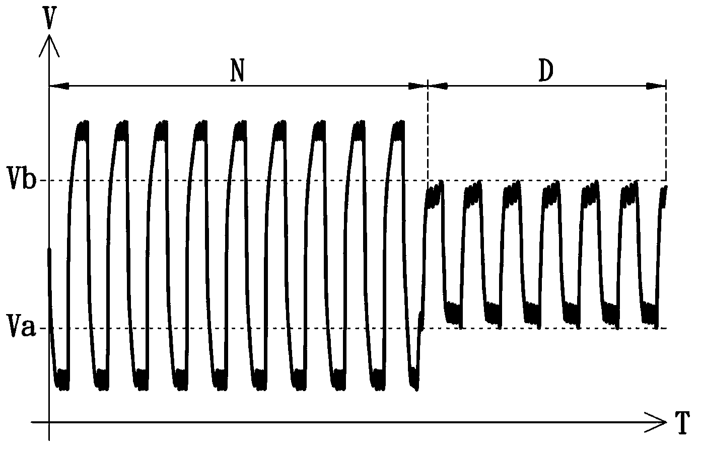
[0104] Figure 2B based on Figure 2A The voltage waveform diagram of the insulation detection circuit of another embodiment of the present invention. see Figure 2B , Figure 2B Shown are the voltage waveforms of the second capacitor 120 in the normal state and the abnormal state. When the insulation state between the high-voltage power supply 9 and the low-voltage power supply 8 is normal, the detection unit 16 detects that the voltage waveform of the second capacitor 120 is as follows: Figure 2B The time section N; when the insulation state between the high-voltage power supply 9 and the low-voltage power supply 8 is abnormal, the detection unit 16 detects that the voltage waveform of the second capacitor 120 is as follows Figure 2B time period D.
[0105] In detail, the voltage or current waveform detected by a general insulation detection circuit is a continuous wave with no obvious voltage drop or a continuous wave with no obvious current difference, so it is diffi...
PUM
 Abstract
Description
Claims
Application Information
 - R&D
- Intellectual Property
- Life Sciences
- Materials
- Tech Scout
- Unparalleled Data Quality
- Higher Quality Content
- 60% Fewer Hallucinations
Browse by: Latest US Patents, China's latest patents, Technical Efficacy Thesaurus, Application Domain, Technology Topic, Popular Technical Reports.
© 2025 PatSnap. All rights reserved.Legal|Privacy policy|Modern Slavery Act Transparency Statement|Sitemap|About US| Contact US: help@patsnap.com


