Output protection type PWM boost control circuit

A technology of output protection and circuit, applied in the field of PWM boost control circuit, can solve the problems of poor reliability, low efficiency, high power consumption, etc., and achieve the effect of high power factor, low cost and low power consumption

Inactive Publication Date: 2014-06-11
XIAN ZHIHAI POWER TECH
View PDF0 Cites 2 Cited by
  • Summary
  • Abstract
  • Description
  • Claims
  • Application Information

AI Technical Summary

Problems solved by technology

[0008] The invention provides an output protection type PWM boost control circuit, which mainly solves the problems

Method used


Image

  • Output protection type PWM boost control circuit
  • Output protection type PWM boost control circuit
  • Output protection type PWM boost control circuit

Examples


Example Embodiment

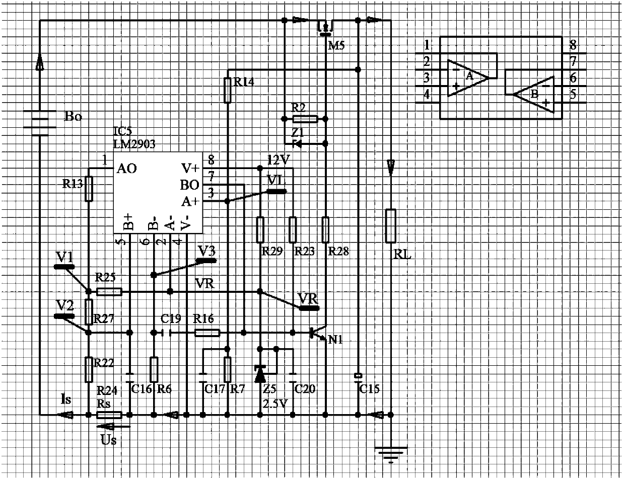
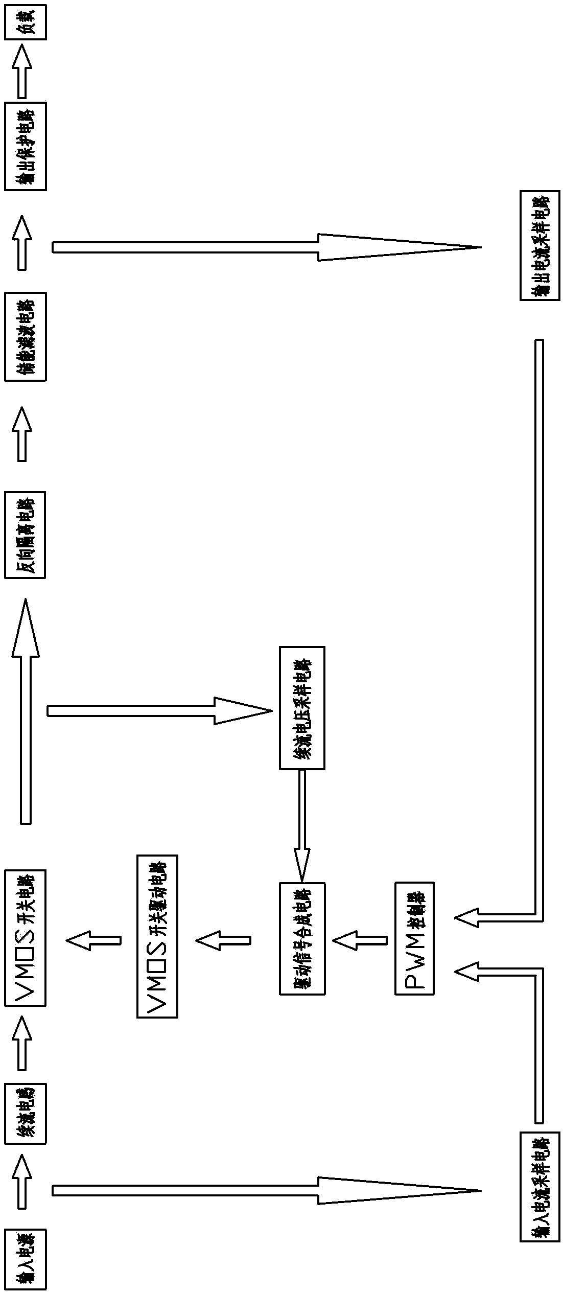
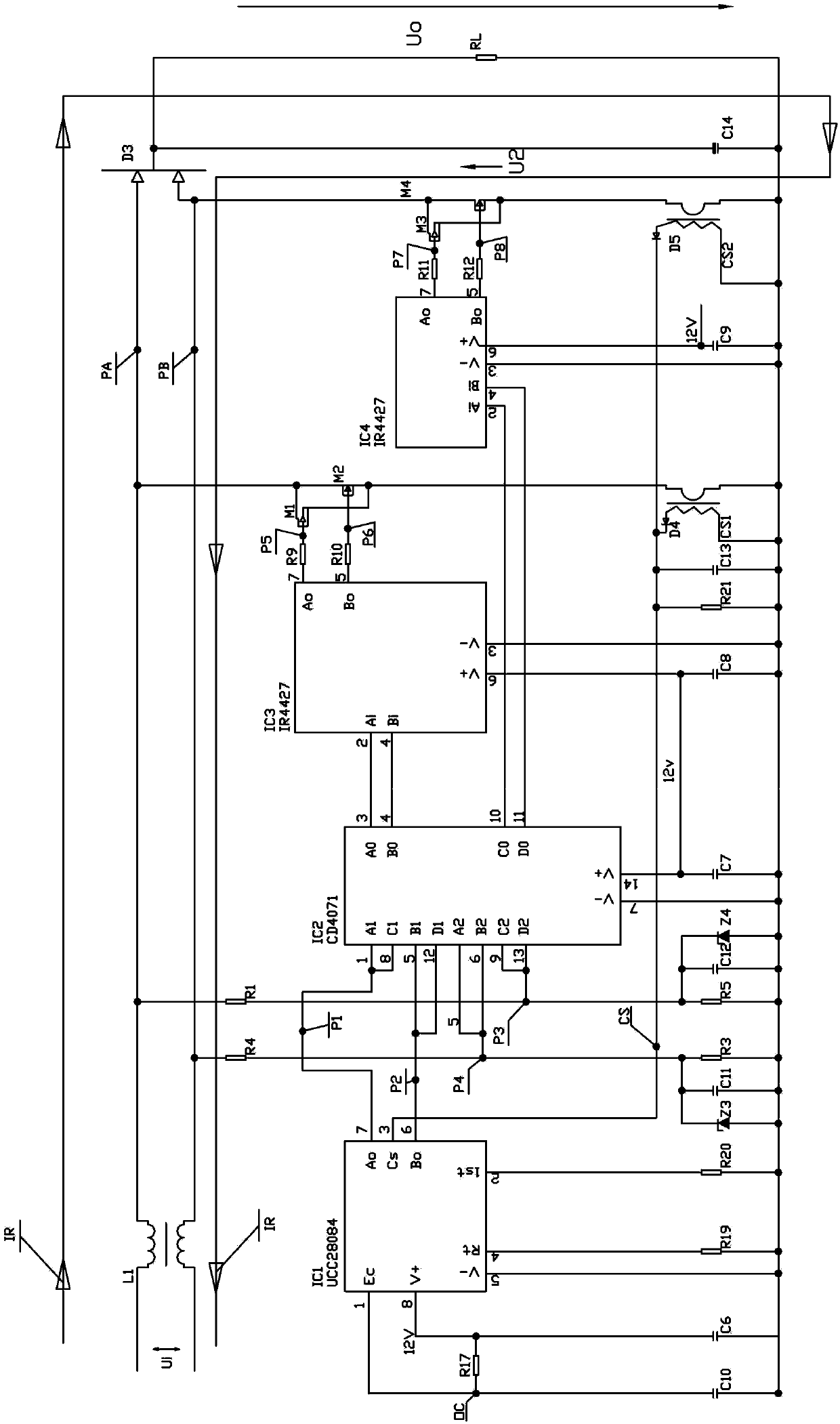
[0022] The output protection type PWM boost control circuit includes a load. The input end of the load is connected to the output end of the input power supply through an energy storage filter circuit, a reverse isolation circuit, a VMOS control circuit, and a freewheeling inductor in sequence; The output end of the filter circuit is connected through the output current sampling circuit and the input end of the width-modulated pulse control circuit, and the output end of the input power supply is connected through the input current sampling circuit and the input end of the width-modulated pulse control circuit. The output terminal of the control circuit is connected to the input terminal of the VMOS switch circuit through the drive signal synthesis circuit and the VMOS switch drive circuit in turn, and the input terminal of the drive signal synthesis circuit is connected to the output terminal of the VMOS switch circuit through the freewheeling voltage sampling circuit; Wide pul...


PUM


Abstract

The invention provides an output protection type PWM boost control circuit. The output protection type PWM boost control circuit mainly solves the problem that an existing low-voltage new energy power adapter is high in power consumption, low in efficiency and poor in reliability. The output protection type PWM boost control circuit comprises two differential-mode symmetric inductors and an output protection circuit, and the two differential-mode symmetric inductors are arranged at the positive end and the negative end of an input power output end respectively. An output current sampling circuit comprises a current sensor CS2, a capacitor C9 and a diode D5, the current sensor CS2 and the diode D5 are connected in series to form a branch circuit, and the capacitor C9 is connected with the branch circuit in parallel. A common cathode diode is adopted by a reverse isolation circuit.

Description

technical field [0001] The invention relates to a PWM boost control circuit, which belongs to the technical field of power conversion. Background technique [0002] In recent years, photovoltaic power generation, wind power generation, battery power supply and other renewable new energy systems with AC low voltage and DC low voltage power supply have been widely used. It is imperative to improve the power supply efficiency, power supply quality and power supply reliability of low voltage new energy power supply systems. [0003] At present, the power conversion known in the art basically adopts: [0004] 1. AC (AC) input, using a full-wave rectifier to rectify the input AC (AC) power to DC (DC) power, and then convert DC / DC to DC (DC) output. This kind of scheme solves the conversion problem of higher input voltage AC power supply and low-power power supply. However, when low-voltage AC power input and high-power power conversion, because the voltage drop of the AC / DC rect...

Claims


Application Information

Patent Timeline
IPC IPC(8): H02M1/088H02M1/32
Inventor 胡家培胡民海
Owner XIAN ZHIHAI POWER TECH
Why Eureka
Try Eureka