Self-walking type corn combine harvester

A combine harvester and self-propelled technology, which is applied to harvesters, agricultural machinery and implements, cutters, etc., can solve problems such as difficulty in exerting high-horsepower engines, blockage of engine cooling water tanks, and engine overheating, so as to improve heat dissipation and ventilation effect, put an end to bracts that cannot be crushed, and facilitate maintenance

Inactive Publication Date: 2014-06-18
SHANDONG GUOFENG MACHINE
View PDF6 Cites 7 Cited by
  • Summary
  • Abstract
  • Description
  • Claims
  • Application Information

AI Technical Summary

Problems solved by technology

[0002] The invention patent of application number 201010241235.1 discloses a self-propelled corn combine harvester. The engine 23 of this machine is a mid-mounted engine, and the power transmission is carried out through a belt. Although the structure is simple, the power output loss is large and it is easy to slip, which is difficult to Make full use of the high-horsepower engine; affected by the design position of the engine, the ear elevator and the ear peeling machine are located above the engine. When the harvesting operation is in progress, the corn husks are easy to fall on the engine, and under the action of a large amount of heat energy accumulated, causing The burning of bracts above the engine will easily cause the blockage of the cooling water tank of the engine, resulting in overheating of the engine, thereby affecting the normal operation of the corn harvester; the driving mode is front drive, which is difficult to cope with harsh working conditions; in addition, the ear box is arranged at the end of the unit At the end, when the ear boxes are filled with harvested corn, the huge weight is almost entirely pressed on the rear axle and guide wheels, resulting in excessive bearing capacity of the rear axle and guide wheels, which affects the steering flexibility of the unit

Method used


Image

  • Self-walking type corn combine harvester
  • Self-walking type corn combine harvester
  • Self-walking type corn combine harvester

Examples


Embodiment Construction

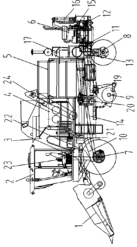
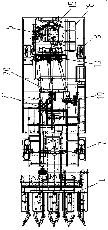
[0013] The specific implementation manners of the present invention will be described below in conjunction with the accompanying drawings. The self-propelled corn combine harvester takes the frame 10 as the carrier, and the upper part of the frame 10 is respectively a corn cutting platform 1, a cab 2, an ear lifter 3, an ear peeler 4, an ear bin 5, engine6. A front axle assembly 7 and a rear axle assembly 8 are respectively arranged at the front and rear ends of the lower part of the frame 10, and a straw crushing and returning machine 9 is arranged between the front axle assembly 7 and the rear axle assembly 8.

[0014] The engine 6 is located at the tail of the self-propelled corn combine harvester. The engine 6 has changed the traditional horizontal layout and adopted a vertical installation layout. The gear box 13 is connected, and the power is divided into three ways to transmit the power to the walking system 14, the straw crushing and returning machine 9, the corn cutt...


PUM


Abstract

Provided is a self-walking type corn combine harvester. A transmission part comprises a front axle assembly arranged at the front end of a rack and a rear axle assembly arranged at the rear end of the rack, an engine is arranged on the upper rear portion of the rear axle assembly, a main power output shaft and an auxiliary power output shaft are connected to an output shaft of the engine, one end of the auxiliary power output shaft is connected with a rotary shaft of a cooling fan, the main power output shaft is connected with a one-to-three transfer gearbox, the one-to-three transfer gearbox is respectively connected with a straw smashing and recycling machine transmission line, a walking gearbox driving line and a main transmission box driving line, the main transmission box driving line is respectively connected with a cluster peeling machine, a corn cutting table and a cluster elevator, and a straw smashing and recycling machine is arranged below the rack and between the front axle assembly and the rear axle assembly. The self-walking type corn combine harvester has the advantages of being reasonable in overall layout, high in straw smashing efficiency, reasonable in transmission line design and good in engine heat dissipation effect.

Description

technical field [0001] The invention relates to the technical field of agricultural harvesting machinery, in particular to a self-propelled corn combine harvester. Background technique [0002] The invention patent of application number 201010241235.1 discloses a self-propelled corn combine harvester. The engine 23 of this machine is a mid-mounted engine, and the power transmission is carried out through a belt. Although the structure is simple, the power output loss is large and it is easy to slip, which is difficult to Make full use of the high-horsepower engine; affected by the design position of the engine, the ear elevator and the ear peeling machine are located above the engine. When the harvesting operation is in progress, the corn husks are easy to fall on the engine, and under the action of a large amount of heat energy accumulated, causing The burning of bracts above the engine will easily cause the blockage of the cooling water tank of the engine, resulting in ove...

Claims


Application Information

Patent Timeline
Patent Type & Authority Applications(China)
IPC IPC(8): A01D41/02A01D69/03
Inventor 鹿秀凤郑振华顾瞻杜国庆翁小青金燕李健
Owner SHANDONG GUOFENG MACHINE
Why Eureka
Try Eureka