Corrugated pipe forming device and corrugated pipe machined through corrugated pipe forming device

A bellows and electromagnetic forming technology, applied in the field of bellows, can solve the problems of not being able to form at one time, complex processing process, high condition requirements, etc., and achieve the effect of fast forming speed, high forming precision and less processing procedures

Inactive Publication Date: 2014-06-18
HUNAN UNIV
View PDF10 Cites 22 Cited by
  • Summary
  • Abstract
  • Description
  • Claims
  • Application Information

AI Technical Summary

Problems solved by technology

[0005] The processing and manufacturing of corrugated pipes in the prior art usually adopts hydroforming, roll forming, mechanical bulging, welding forming, etc., the forming efficiency is low and the process is complicated
For example, in the manufacturing method of the metal bellows in the patent application 201210595118.X, the pipe fittings are heated first, and then liquid is filled into the pipe fittings for expansion. The processing conditions required are high and the working conditions are complicated.
For example, in the manufacturing method of metal bellows in Chinese patent application 200710302010.0, pressure is first applied on the inner side of the pipe to make it bulge and form a concertina-shaped protrusion, and then the corrugated tube is formed by rolling. The processing process is complicated and cannot be formed at one time.

Method used


Image

  • Corrugated pipe forming device and corrugated pipe machined through corrugated pipe forming device
  • Corrugated pipe forming device and corrugated pipe machined through corrugated pipe forming device
  • Corrugated pipe forming device and corrugated pipe machined through corrugated pipe forming device

Examples


Embodiment Construction

[0048] The technical solutions in the embodiments of the present invention will be further illustrated and described below in conjunction with the drawings in the embodiments of the present invention. Apparently, the described embodiments are only some of the embodiments of the present invention, but not all of them. Based on the embodiments of the present invention, all other embodiments obtained by persons of ordinary skill in the art without making creative efforts belong to the protection scope of the invention.

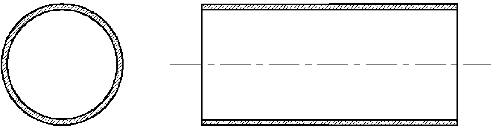
[0049] Such as figure 1 As shown, the metal thin-walled tubes provided in many embodiments of the present invention have good electrical conductivity, such as copper, aluminum alloy and the like. The metal material used in this embodiment is 3A21 aluminum alloy, its length is 150 mm, its diameter is 50 mm, and its thickness is 1.2 mm.

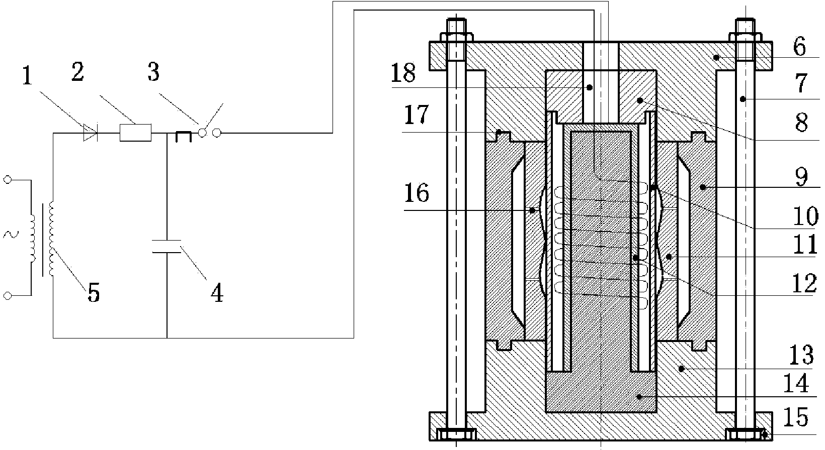
[0050] Such as figure 2 As shown, the electromagnetically formed energy-absorbing bellows forming device used in the embodim...


PUM

PropertyMeasurementUnit
lengthaaaaaaaaaa
diameteraaaaaaaaaa
thicknessaaaaaaaaaa

Abstract

The invention discloses a corrugated pipe forming device based on electromagnetic forming. The corrugated pipe forming device is characterized by comprising a rectifier (1), a resistor (2), a switch (3), a capacitor (4), a boosting transformer (5), an upper fixing plate (6), fixing bolts (7), a pressing block (8), a mold base (9), a constraint mold (11), a coil (12), a lower fixing plate (13), a T-shaped platform (14), trapezoid holes (15), exhaust holes (16), fixing grooves (17) and a wire hole (18). In addition, a thin-wall energy-absorption corrugated pipe forming method based on the electromagnetic forming principle has the advantages that the number of machining processes is small, machining efficiency is high, forming accuracy is high, the pipe forming speed is high, a thin-wall metal pipe can be formed at a high strain rate, the plasticity of metal materials is improved greatly, and the yield strength of the materials is enhanced substantially. By changes of the shape of the constraint mold in the forming device, different wave shapes can be formed, and machining flexibility of the forming device is high.

Description

technical field [0001] The invention relates to a bellows processing technology, in particular to a device for processing metal energy-absorbing bellows based on the principle of electromagnetic forming and a bellows obtained based on the processing device. Background technique [0002] Metal thin-walled components, as energy-absorbing components, are widely used in collision kinetic energy dissipation systems of almost all vehicles such as automobiles, ships, and airplanes. Metal thin-walled components mainly rely on their own plastic deformation to absorb the impact kinetic energy in vehicle collisions. When subjected to impact loads, their failure mode is stable, and their own plastic deformation absorbs and consumes energy, and produces a certain amount of crushing. Stroke, so as to achieve the purpose of absorbing the kinetic energy of the vehicle, reducing the damage of the occupants in the vehicle, and reducing the deceleration of the vehicle. [0003] Thin-walled ci...

Claims


Application Information

Patent Timeline
Patent Type & Authority Applications(China)
IPC IPC(8): B21D26/14
Inventor 孙光永崔俊佳李光耀康贺贺
Owner HUNAN UNIV
Why Eureka
Try Eureka