Boiler barrel welding method
A welding method and drum technology, applied in welding equipment, arc welding equipment, manufacturing tools, etc., can solve the problem of high repair rate, achieve the effects of reducing repair rate, ensuring product quality, and less air holes
- Summary
- Abstract
- Description
- Claims
- Application Information
AI Technical Summary
Problems solved by technology
Method used
Image

Examples
specific Embodiment approach 1
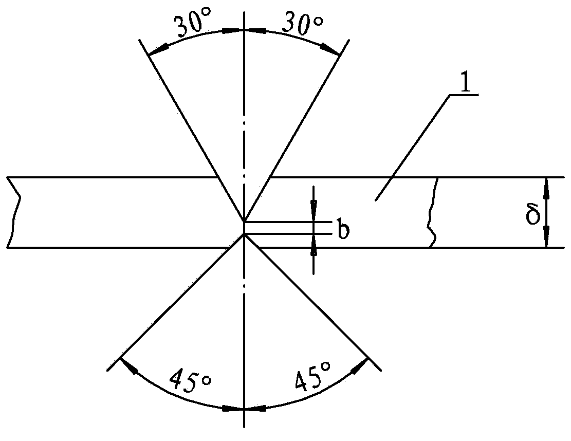
[0012] Specific implementation mode one: combine figure 1 Describe this embodiment, this embodiment is the welding method of the first cylinder joint, the method is realized through the following steps: Step 1, the thickness δ of the first cylinder joint 1 to be welded is 26 mm to 28 mm, Both the inside and outside of the barrel joint 1 are grooved, the inside groove is 30°, the outside groove is 45°, the first blunt edge b between the inside groove and the outside groove is 4mm~5mm, and the inside groove Grind and clean both sides and both sides of the outer groove; step 2, roll the first welded tube section 1, and the butt joints must not have gaps; step 3, use the first rolled tube section 1 to be welded Gas shielded welding is performed on the outer side for spot welding, and the spot welding length is 20mm to 40mm; step 4, the inner side of the first welded cylinder section 1 is fully welded by submerged arc automatic welding, where the diameter of the welding wire is 4.0...
specific Embodiment approach 2
[0013] Specific implementation mode two: combination figure 1 To describe this embodiment, the spot welding length in Step 3 of this embodiment is 25 mm to 35 mm. Other steps are the same as in the first embodiment.
specific Embodiment approach 3
[0014] Specific implementation mode three: combination figure 1 To describe this embodiment, the spot welding length in Step 3 of this embodiment is 30mm. Other steps are the same as those in Embodiment 1 or 2.
PUM
| Property | Measurement | Unit |
|---|---|---|
| Diameter | aaaaa | aaaaa |
| Length | aaaaa | aaaaa |
Abstract
Description
Claims
Application Information
 - Generate Ideas
- Intellectual Property
- Life Sciences
- Materials
- Tech Scout
- Unparalleled Data Quality
- Higher Quality Content
- 60% Fewer Hallucinations
Browse by: Latest US Patents, China's latest patents, Technical Efficacy Thesaurus, Application Domain, Technology Topic, Popular Technical Reports.
© 2025 PatSnap. All rights reserved.Legal|Privacy policy|Modern Slavery Act Transparency Statement|Sitemap|About US| Contact US: help@patsnap.com