
Corrosion-resistant pneumatic spray head and manufacture method thereof

A gas spray head and corrosion-resistant technology, applied in gaseous chemical plating, superimposed layer plating, coating, etc., can solve the problem that ceramic particles cannot reach places that cannot be seen and can be coated to shorten the service life , line of sight effect and other issues

Active Publication Date: 2014-06-18
ADVANCED MICRO FAB EQUIP INC CHINA
View PDF4 Cites 10 Cited by
  • Summary
  • Abstract
  • Description
  • Claims
  • Application Information

AI Technical Summary

Problems solved by technology

The methods of coating ceramic coatings commonly used in the prior art are methods such as plasma sputtering and chemical vapor deposition. These methods all have the problem of line-of-sight effect, that is, the ceramic particles used for spraying cannot reach places that are out of sight and are harmful to the environment. It is coated, and in deep holes or grooves, etc., it is difficult to prepare ceramic coatings
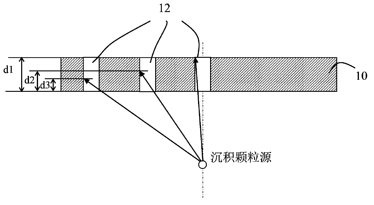
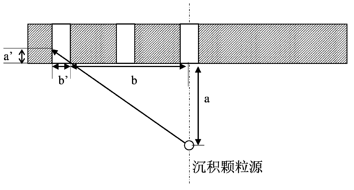
like figure 1 As shown, since the source of ceramic particles used for deposition or spraying is usually fixed, the area of ​​the inner surface of the vent hole at a position farther away from the source of ceramic particles is less coated by ceramic coating, even if the vent hole close to the source of ceramic particles Pores, and only one end close to the source of ceramic particles can be coated with ceramic coating, and cannot be completely coated with ceramic coating
[0004] Vent holes that are not fully finished with an anti-corrosion coating are highly susceptible to corrosion when placed in a plasma, making the gas shower head vulnerable to damage and shortening life
In addition, when the plasma in the reaction chamber splashes to the position where the inner surface of the vent hole is not coated with an anti-corrosion layer, it is also easy to generate particle pollution, which falls on the surface of the substrate and affects the reaction process.

Method used


Image

  • Corrosion-resistant pneumatic spray head and manufacture method thereof
  • Corrosion-resistant pneumatic spray head and manufacture method thereof
  • Corrosion-resistant pneumatic spray head and manufacture method thereof

Examples


Embodiment Construction

[0023] The specific embodiments of the present invention will be described below with reference to the accompanying drawings, and a gas shower head and its manufacturing method are provided, which can improve the anti-corrosion and particle pollution performance of the gas shower head.

[0024] In the prior art, in order to protect the gas shower head from being eroded by plasma, a plasma erosion-resistant coating, such as a ceramic coating, is usually coated on the surface of the gas shower head main body. Methods for coating ceramic coatings include physical vapor deposition, plasma spraying, etc. Among them, physical vapor deposition is widely used because of its simple operation and low requirements on spraying equipment and environment. When the gas shower head is coated with a corrosion-resistant layer by the physical vapor deposition method, a ceramic deposition source is arranged under the surface of the gas shower head to be coated, and the ceramic in the ceramic depos...


PUM


Abstract

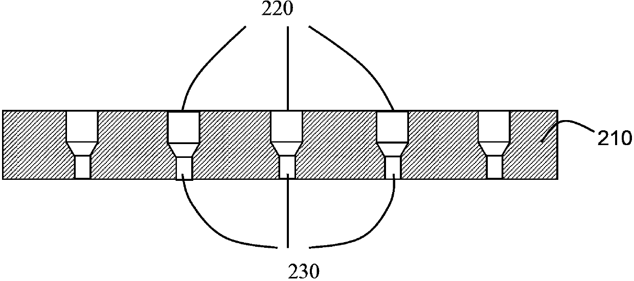
The invention discloses a corrosion-resistant pneumatic spray head and a manufacture method thereof. The manufacture method of the corrosion-resistant pneumatic spray head is characterized in that an air through hole of the traditional pneumatic spray head is divided into two sections with different diameters, and thus the depth of a coating entering the air through hole can be increased without influencing the flow rate of gas; both the upper surface and the lower surface of the pneumatic spray head are coated with ceramic coatings, so that the inner surface of the air through hole is completely coated with the corrosion-resistant ceramic coating, so as to prevent the sidewall of the air through hole from being impacted by energy-carrying particles, and as a result, the service life of the pneumatic spray head is prolonged.

Description

technical field [0001] The present invention relates to plasma processing components and, in particular, to a corrosion resistant plasma processing component. Background technique [0002] In a plasma processing chamber, a gas showerhead is often used to inject reactant gases into the reaction chamber. In certain plasma processing chambers, such as capacitively-coupled plasma chambers, the gas shower head can also perform the function of the electrode. However, during the process, the gas shower head is exposed to In the plasma and eroded by the active components in the plasma, such as halogen plasma CF4, Cl2, etc. This phenomenon is particularly troublesome for gas shower heads made of silicon-based materials that easily react with halogen gas and the reactant is gas, or metal materials such as aluminum or aluminum alloy. [0003] In the prior art, various anti-erosion coatings have been proposed and verified in order to protect the gas shower head from being eroded by pl...

Claims


Application Information

Patent Timeline
Patent Type & Authority Applications(China)
IPC IPC(8): C23C16/455C23C28/00
Inventor 张力贺小明浦远倪图强
Owner ADVANCED MICRO FAB EQUIP INC CHINA
Learn More