Plasma processing equipment and its lower electrode mechanism

An electrode mechanism and plasma technology, applied in gaseous chemical plating, metal material coating process, coating, etc., can solve the problem of poor contact between the grounding column and the carrier plate, thermal deformation of the grounding column support, and the effect of the electrode under the carrier plate. Reduction and other problems to achieve the effect of solving poor grounding, good contact, and reducing equipment costs

Active Publication Date: 2016-04-27
BEIJING NAURA MICROELECTRONICS EQUIP CO LTD
View PDF2 Cites 0 Cited by
  • Summary
  • Abstract
  • Description
  • Claims
  • Application Information

AI Technical Summary

Problems solved by technology

[0005] However, the disadvantages of the prior art are: 1. The thermal deformation of the grounding column support is serious, resulting in inconsistent heights of some grounding columns, and poor contact between some grounding columns and the carrier plate, resulting in discharge and sparking between the carrier plate and the parts in the reaction chamber during the process.
2. The structure of the grounding post is complex. Due to the errors in the processing, installation and debugging of the grounding post end cover, the connecting rod of the grounding post and the grounding post support, as well as the deformation caused by high temperature heating, the path of the current is different, resulting in different potential distributions. uniform
Affect the grounding effect
4. The support of the grounding column is grounded to the bottom plate of the chamber by connecting wires, but after the carrier board has been processed for a long time, the upper and lower surfaces of the carrier board will be coated with an insulating SiNx film, so that the effect of the lower electrode of the carrier board is reduced or even Loss, causing RF to directly discharge with the lower cover, affecting the quality of wafer coating

Method used


Image

  • Plasma processing equipment and its lower electrode mechanism
  • Plasma processing equipment and its lower electrode mechanism
  • Plasma processing equipment and its lower electrode mechanism

Examples


Embodiment Construction

[0031] Embodiments of the present invention are described in detail below, examples of which are shown in the drawings, wherein the same or similar reference numerals designate the same or similar elements or elements having the same or similar functions throughout. The embodiments described below by referring to the figures are exemplary only for explaining the present invention and should not be construed as limiting the present invention.

[0032]In describing the present invention, it should be understood that the terms "center", "longitudinal", "transverse", "upper", "lower", "front", "rear", "left", "right", " The orientations or positional relationships indicated by "vertical", "horizontal", "top", "bottom", "inner", "outer", etc. are based on the orientation or positional relationships shown in the drawings, and are only for the convenience of describing the present invention and simplifying Describes, but does not indicate or imply that the device or element referred ...


PUM


Abstract

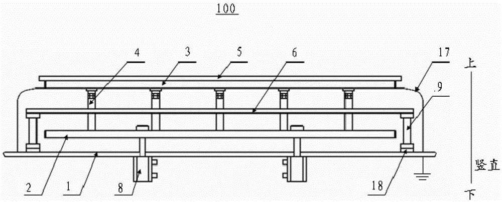
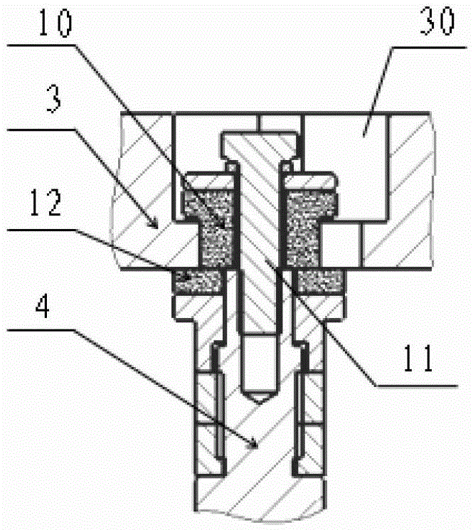
The invention discloses a lower electrode mechanism of plasma processing equipment. The lower electrode mechanism comprises a lower electrode base plate, an ground pole supporting member, a ground pole, a support plate supporting member, a support plate, and a heater, and the lower electrode base plate is grounded. The ground pole supporting member is arranged above the lower electrode base plate, and is capable of being vertically lifted up and down. The upper end of the ground pole is connected to the support plate supporting member, and the lower end of the ground pole is connected to the ground pole supporting member. The support plate supporting member is arranged above the ground pole supporting member, is grounded, and is electrically insulated from the ground pole. The support plate is supported by the support plate supporting member, and is directly grounded through the support plate supporting plate. The heater is arranged between the support plate supporting member and the ground pole supporting member. The lower electrode mechanism has the advantages of simple ground current route and high repeatability, and solves the problem of imperfect earth of lower electrode. The invention also discloses plasma processing equipment comprising the lower electrode mechanism.

Description

technical field [0001] The invention relates to the field of semiconductor equipment manufacturing, in particular to a plasma processing equipment and its lower electrode mechanism. Background technique [0002] In the process chamber of the current plasma-enhanced chemical vapor deposition system (PECVD system) in the solar industry, such as Image 6 As shown, the chamber bottom plate 202 has been grounded, and the potential is the same as the ground. The grounding column 204, the cylinder 201 and the grounding column support 207 for supporting the grounding column form the lower electrode lifting device, and the grounding column 204 passes through the grounding wire 203 and The chamber floor 202 is connected. The carrier board 205 is placed on the ground post 204 so that the carrier board 205 is grounded. The heater support 208 supports the heater 206 to heat a specific gas entering the process chamber. The process chamber is in a vacuum environment, and after being heat...

Claims


Application Information

Patent Timeline
Patent Type & Authority Patents(China)
IPC IPC(8): C23C16/50
Inventor 李萌
Owner BEIJING NAURA MICROELECTRONICS EQUIP CO LTD
Why Eureka
Try Eureka