
Hydraulic supporting device of suspended top beams for roadways in shed

A hydraulic support and roadway technology, which is applied to the mine roof support, mining equipment, earthwork drilling and mining, etc., can solve the problems of too many single pillar drilling bottoms, difficulty in greatly increasing the speed of support and withdrawal, and a large number of users , to achieve the effect of maintaining the height and section of the roadway, high promotion and practical value, and convenient installation and removal

Inactive Publication Date: 2014-06-18
欧亚伟 +1
View PDF5 Cites 15 Cited by
  • Summary
  • Abstract
  • Description
  • Claims
  • Application Information

AI Technical Summary

Problems solved by technology

[0004] (1) Low support strength: For places with high pressure on the roof, when the bottom plate is soft, the bottom of the single pillar will be drilled more, which will not achieve the reinforcement effect, resulting in serious deformation of the roadway
[0005] (2) Slow support speed: due to the difficulty of increasing the support and withdrawal speed of single hydraulic props and top beams, the working speed is restricted
[0006] (3) High labor intensity: frequent support and withdrawal of single pillars and top beams, and all of them are manpower, resulting in many users and high labor intensity
[0007] (4) Poor safety: the process is complicated, there are many manual operations, and the probability of accidents is relatively high

Method used


Image

  • Hydraulic supporting device of suspended top beams for roadways in shed
  • Hydraulic supporting device of suspended top beams for roadways in shed
  • Hydraulic supporting device of suspended top beams for roadways in shed

Examples


Embodiment Construction

[0021] The following combined with the attachment to further explain the present invention:

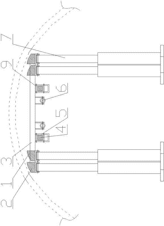
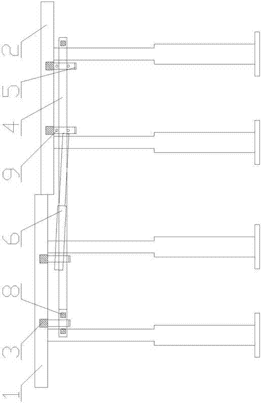
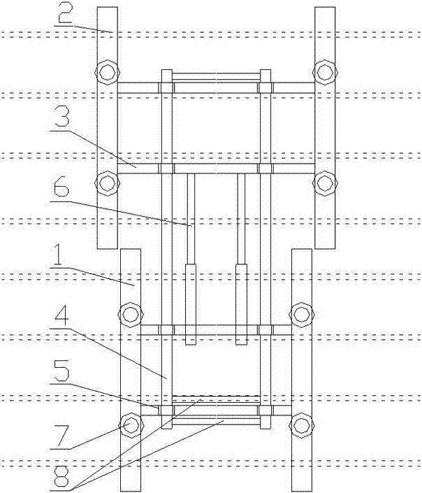
[0022] like figure 1 As well as figure 2 As well as image 3 It shows that the shed lane lanes are used to move the tip of the hydraulic support device, including the front bracket and the rear bracket.The parallel rear vertical beam 1; the peaceful rear section beam 1 between the parallel front beam 2 between the parallel front beam 2; there are two below the beam 3 of each beam 3 of each beam 3The beam slide 5, located in the Tuliang 4 within the beam slide 5 to connect the front bracket with the rear bracket; the Beiliang 4 played a role in supporting the weight and track of the bracket during the shift process;

[0023] The rear vertical beams 1. The hinge with 7 hydraulic columns below the second vertical beam 2, respectively. The support height of the oil cylinder support is adjusted according to the height of the lane lane.

[0024] The adjacent beams connected to the adjacent beams...


PUM


Abstract

The invention discloses a hydraulic supporting device of suspended top beams for roadways in a shed. The hydraulic supporting device comprises two parts, i.e., a front-section bracket and a rear-section bracket, wherein the front-section bracket comprises two parallel front-section longitudinal beams (2); the rear-section bracket comprises two parallel rear-section longitudinal beams (1); four cross beams (3) are arranged between the parallel front-section longitudinal beams (2) and the parallel rear-section longitudinal beams (1); two supporting-beam sliding grooves (5) are respectively arranged under each cross beam (3); the front-section bracket and the rear-section bracket are connected by supporting beams (4) in the supporting-beam sliding grooves (5). The hydraulic supporting device disclosed by the invention has the advantages that the structure is simple, the bearing capability is high, the mechanical degree is high, the full-hydraulic control is realized, the stability of the bracket is good, the installation and removal are convenient, no base is arranged and pedestrians of the roadway are not influenced. By adoption of the brackets, the roadways in the advanced stress range of two roadways on a stoping working face can be effectively reinforced, the heights and the sections of the roadways can be maintained, the self movement along with the propulsion of the working face can be realized and the promotional and practical values are higher.

Description

Technical field [0001] The present invention involves a kind of subordinate support equipment for coal mines. It is specifically for a concentrated area suitable for coal mine frame sheds, especially the lane lanes within the scope of the impact of coal mining work surface.Increase the touches of the beam of the lane lane pressure resistance capacity. Background technique [0002] Article 50 of the "Coal Mine Safety Regulations" stipulates that within the scope of the impact of all safety exports to the connection between the safety exit of the coal mining surface and the analogy of the roadway, the support must be strengthened;When recycling the bracket, the bracket within a range of 5 meters must be reinforced.At the same time, as the depth of the mining of coal mines has increased, it has gradually entered deep mining, and the appearance of the ore pressure is becoming more and more obvious. The lane lane deformation is severe, and the requirements for the reinforcement of the...

Claims


Application Information

Patent Timeline
IPC IPC(8): E21D23/04E21D23/16
Inventor 欧亚伟
Owner 欧亚伟
Learn More