
Combustion chamber of aero-engine and its aero-engine

A technology of aero-engine and combustion chamber, which is applied in the direction of combustion chamber, continuous combustion chamber, combustion method, etc., to achieve the effect of shortening length, ensuring reliable operation and prolonging service life

Active Publication Date: 2016-02-10
AECC COMML AIRCRAFT ENGINE CO LTD
View PDF5 Cites 0 Cited by
  • Summary
  • Abstract
  • Description
  • Claims
  • Application Information

AI Technical Summary

Problems solved by technology

The comprehensive performance and structural layout of modern aero-engine combustors have reached a very high level, but there are still a lot of problems and challenges

Method used


Image

  • Combustion chamber of aero-engine and its aero-engine
  • Combustion chamber of aero-engine and its aero-engine
  • Combustion chamber of aero-engine and its aero-engine

Examples


Embodiment Construction

[0044] The making and using of the embodiments are discussed in detail below. It should be understood, however, that the specific embodiments discussed are merely illustrative of specific ways to make and use the invention, and do not limit the scope of the invention.

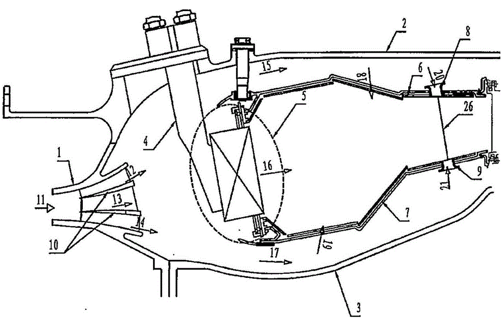
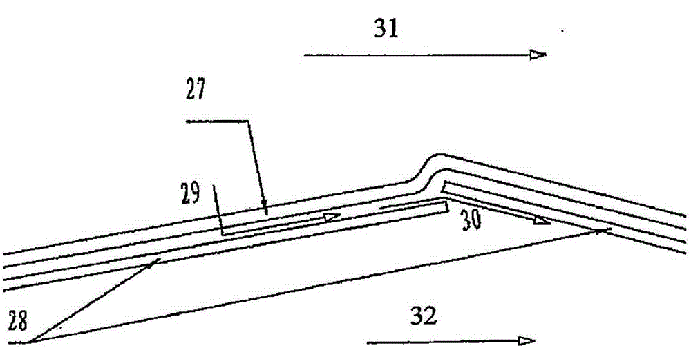
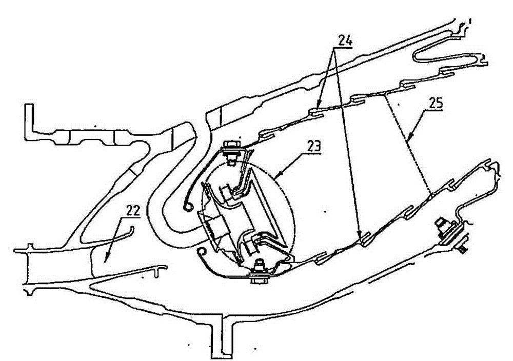
[0045] figure 1 Shown is an aeroengine combustor according to an exemplary but non-limiting embodiment of the present invention: multi-channel inlet diffuser, center staged lean head, ceramic matrix composite floating walls, flame tube volume reduction And the shape of the flame tube that shrinks quickly in the rear section and the hedging and mixing hole array.

[0046] see figure 1 , the aero-engine combustor consists of a multi-channel inlet diffuser 1, a combustor outer casing 2, a combustor inner casing 3, a fuel nozzle 4, and a flame tube. Fuel enters the flame tube through the fuel nozzle 4, and the flame tube is located between the outer casing 2 and the inner casing 3, including the flame tube head ...


PUM


Abstract

The invention provides an aerial engine combustion chamber and an aerial engine comprising the same. The aerial engine combustion chamber comprises an internal casing, an external casing, a flame tube, a fuel spray nozzle and a multi-channel inlet diffuser. Air compressed by an air compressor enters the combustion chamber through the multi-channel inlet diffuser and divided into outer flow, middle flow and inner flow, wherein the outer flow flows into the outer ring cavity between the external casing and an outer flame tube to provide cooling gas and mixed gas penetrating an outer mixing hole array for the outer flame tube, the middle flow flows into the head portion of the flame tube to provide cooling gas and combustion air for the head portion of the flame tube, and the inner flow flows into the inner ring cavity between the internal casing and an inner flame tube to provide cooling gas and mixed gas penetrating an inner mixing hole array for the inner flame tube. The aerial engine combustion chamber can control pollution discharge, prolong the service life of the flame tube at high temperature, improve the outlet temperature distribution and adjustment capabilities of the combustion chamber and guarantee the reliable operation of the combustion chamber.

Description

technical field [0001] The invention relates to the technical field of engines, in particular to an aeroengine combustion chamber realizing low pollution and long life and an aeroengine comprising the combustion chamber. Background technique [0002] The combustion chamber is one of the essential components of a modern aero-engine, where the chemical energy contained in the fuel is transformed into heat energy through a combustion chemical reaction, forming high-temperature combustion products, and driving the turbine to do work. The comprehensive performance and structural layout of modern aero-engine combustors have reached a very high level, but there are still a lot of problems and challenges. The continuous development and application of new materials, new processes, new structures, and new concepts can ensure its everlasting success. [0003] As the atmospheric environmental issues are receiving more and more attention worldwide, the requirements for the limitation of...

Claims


Application Information

Patent Timeline
Patent Type & Authority Patents(China)
IPC IPC(8): F23R3/42F23R3/04F23R3/28
Inventor 刘雯佳李彬郭德三胡莹超
Owner AECC COMML AIRCRAFT ENGINE CO LTD
Learn More