Permanent magnet synchronous motor torque control method based on sliding mode flux linkage observer

A permanent magnet synchronous motor, flux linkage observer technology, applied in observer control, single motor speed/torque control, torque ripple control, etc., can solve the problem of stator flux linkage estimation accuracy drop, torque and flux linkage ripple It can eliminate the problems of large motor power factor and reduce the power factor of the motor, so as to achieve the effect of eliminating the position sensor, reducing the torque and flux pulsation, and reducing the motor loss.

Active Publication Date: 2014-06-18
SOUTHEAST UNIV
View PDF3 Cites 44 Cited by
  • Summary
  • Abstract
  • Description
  • Claims
  • Application Information

AI Technical Summary

Problems solved by technology

However, in the voltage model, due to the integration of the back EMF of the stator winding, when the motor is running at low speed, the estimation accuracy of the stator flux linkage is seriously reduced, and even the system cannot work; in the current model, the rotor position needs to be known, adding additional position sensor, which will increase the cost of the control system, reduce the reliability of

Method used


Image

  • Permanent magnet synchronous motor torque control method based on sliding mode flux linkage observer
  • Permanent magnet synchronous motor torque control method based on sliding mode flux linkage observer
  • Permanent magnet synchronous motor torque control method based on sliding mode flux linkage observer

Examples


Embodiment Construction

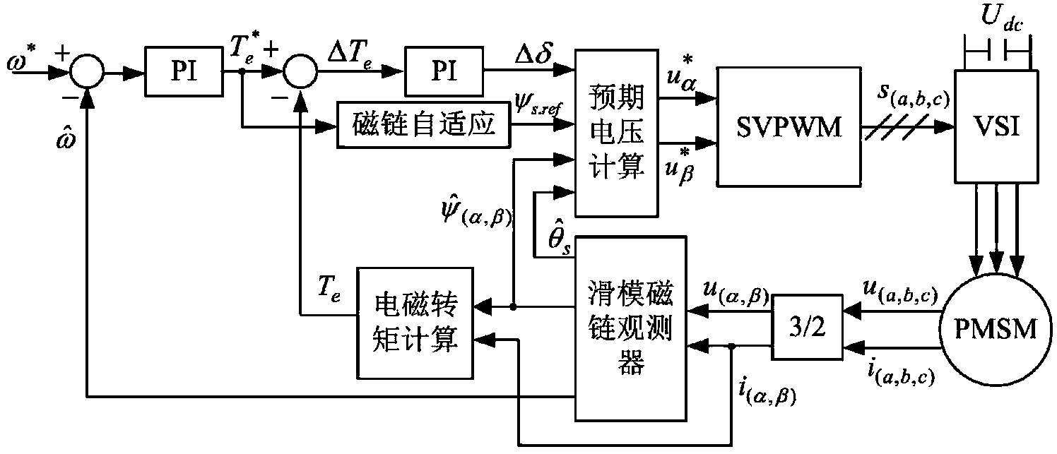
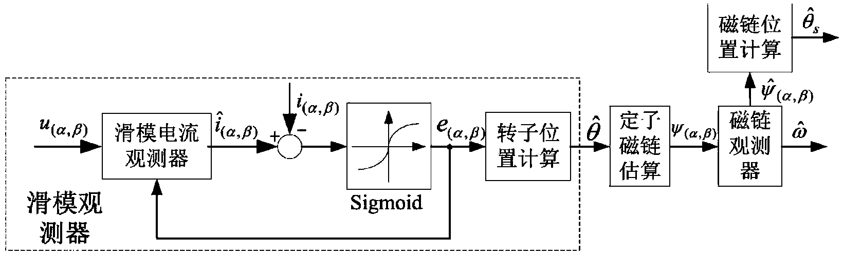
[0027] Combine below figure 1 , figure 2 The technical scheme of the present invention is described in further detail.

[0028] Such as figure 1 As shown, the permanent magnet synchronous motor torque control system based on the sliding mode flux observer in the present invention includes a permanent magnet synchronous motor, 3 / 2 coordinate transformation, sliding mode flux observer, electromagnetic torque calculation, speed PI regulator, Torque PI regulator, flux linkage adaptation, expected voltage calculation, SVPWM module and inverter.

[0029] The specific implementation steps of the permanent magnet synchronous motor torque control method based on the sliding mode flux observer in the present invention are as follows:

[0030] Step 1), detect the three-phase current i of the permanent magnet synchronous motor a i b i c and three-phase voltage u a , u b , u c , after the 3 / 2 coordinate transformation, the current component i in the two-phase static AC coordinate...


PUM


Abstract

The invention discloses a permanent synchronization motor torque control method based on a sliding mode flux linkage observer. Direct torque control is performed on a permanent synchronization motor through a 3/2 coordinate conversion module, the sliding mode flux linkage observer, an electromagnetic torque calculation module, a rotating speed PI adjustor, a torque PI adjustor, a flux linkage self-adaptation module, an expected voltage calculation module, an SVPWM module and an inverter. The sliding mode flux linkage observer is adopted for estimating the size, phase and rotator speed of stator flux linkage, and set torque is processed through the flux linkage self-adaptation module to obtain a set value of the stator flux linkage. Expected voltage calculation is performed on size and phase estimation values and the set value of the stator flux linkage and the output quantity of the torque PI adjustor, so that two-phase alternating-current voltage reference values on a two-phase static coordinate system are obtained, and then through SVPWM conversion, a switching signal is obtained to drive the voltage source inverter to achieve direct torque control over the permanent synchronization motor.

Description

technical field [0001] The invention belongs to the field of permanent magnet motor control, in particular to a permanent magnet synchronous motor torque control system based on a sliding mode flux observer. Background technique [0002] Permanent magnet synchronous motors have the advantages of small size, high efficiency, easy maintenance and strong adaptability to the environment, and are widely used in many high-performance drive fields. Direct torque control has attracted much attention because of its fast torque response, simple system structure and strong robustness to parameter changes. The stator flux linkage needs to be obtained in the direct torque control of the permanent magnet synchronous motor, and the accuracy of the flux linkage signal determines the control performance of the system. Therefore, how to accurately observe the stator flux linkage is particularly important for the high-performance permanent magnet synchronous motor direct torque control speed ...

Claims


Application Information

Patent Timeline
IPC IPC(8): H02P6/08H02P6/10H02P23/12H02P25/02
Inventor 樊英张丽夏子朋顾玲玲
Owner SOUTHEAST UNIV
Why Eureka
Try Eureka