Phase-locked loop locking indication circuit and phase-locked loop

A technology of locking indication and phase-locked loop, which is applied in the direction of electrical components, automatic power control, etc., and can solve the problems of adding complex circuit locking indications, etc.

Active Publication Date: 2014-06-18
BEIJING RUNKE GENERAL TECH
View PDF6 Cites 6 Cited by
  • Summary
  • Abstract
  • Description
  • Claims
  • Application Information

AI Technical Summary

Problems solved by technology

[0005] In view of this, the present invention provides a phase-locked loop lock indication circuit and a phase-locked loop to solve the problem that the prior art needs to add additional complex circuits to be suitable for lock indication under high output frequency conditions

Method used


Image

  • Phase-locked loop locking indication circuit and phase-locked loop
  • Phase-locked loop locking indication circuit and phase-locked loop
  • Phase-locked loop locking indication circuit and phase-locked loop

Examples


Embodiment Construction

[0032] The following will clearly and completely describe the technical solutions in the embodiments of the present invention with reference to the accompanying drawings in the embodiments of the present invention. Obviously, the described embodiments are only some, not all, embodiments of the present invention. Based on the embodiments of the present invention, all other embodiments obtained by persons of ordinary skill in the art without making creative efforts belong to the protection scope of the present invention.

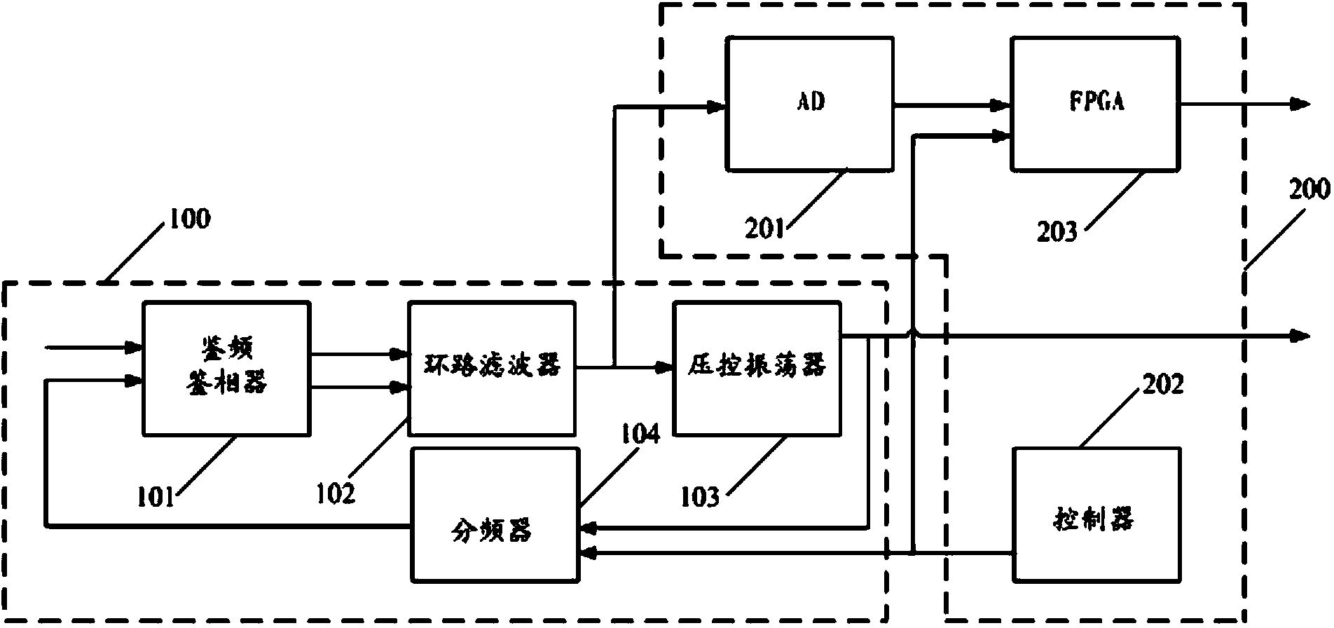
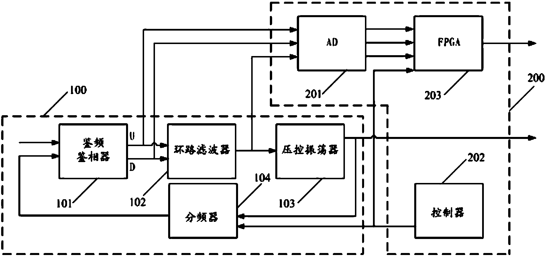
[0033] The invention provides a phase-locked loop lock indication circuit to solve the problem in the prior art that an additional complex circuit is required to be suitable for lock indication under the condition of high output frequency.

[0034] Specifically, such as figure 1 As shown, the phase-locked loop 100 includes: a frequency and phase detector 101, a loop filter 102 connected with the frequency and phase detector 101, a voltage-controlled oscillator...


PUM


Abstract

The invention discloses a phase-locked loop locking indication circuit. An analog-digital converter receives a voltage control signal, conducts analog-digital conversion on the voltage control signal and outputs the voltage control signal; a frequency control signal is output by a controller; the voltage control signal acquired after analog-digital conversion and the frequency control signal are received by a field programmable logic array, and when the difference between the voltage control signal acquired after analog-digital conversion and the frequency control signal is smaller than a first threshold value, a locking indication signal is output, and locking indication of the phase-locked loop is achieved; because locking indication is achieved by the phase-locked loop locking induction circuit by detecting the voltage control signal and the frequency control signal and is not related to the value of the output frequency of the phase-locked loop, engineering application on broadband and high frequency application occasions can be achieved, and the phase-locked loop locking indication circuit can be applied to locking indication under high output frequency or broadband frequency synthesis conditions without additional complex circuits.

Description

technical field [0001] The invention relates to the technical field of power electronics, in particular to a phase-locked loop lock indicating circuit and a phase-locked loop. Background technique [0002] A phase-locked loop (PLL for short) has many advantages in implementing frequency synthesis, such as a simple circuit, small size, and flexible frequency configuration, so it is widely used. In high-speed wired communication, it is used for clock generation, clock recovery, etc.; in wireless communication, it is used for the generation of radio frequency local oscillator frequency. [0003] The lock indication function indicates whether the phase-locked loop can be locked normally, which is very important for the status indication and troubleshooting of the phase-locked loop itself and the system to which the phase-locked loop is applied. In the case that the phase detection frequency is not very high, the general phase-locked loop chip itself has the locking indication f...

Claims


Application Information

Patent Timeline
Patent Type & Authority Applications(China)
IPC IPC(8): H03L7/08H03L7/085H03L7/18
Inventor 梁亮
Owner BEIJING RUNKE GENERAL TECH
Why Eureka
Try Eureka