
A marker, its manufacturing method and a positioning system made of the marker

A positioning system and marker technology, applied in the field of medical equipment, can solve the problems of high pneumothorax, the tail end of the coil cannot ensure the exposure of the pleura, and gas embolism, etc., so as to achieve a slim implant structure, easy to observe or touch, and a small delivery device. Effect

Active Publication Date: 2015-11-18
常州爱康臻医疗科技有限公司 +1
View PDF3 Cites 3 Cited by
  • Summary
  • Abstract
  • Description
  • Claims
  • Application Information

AI Technical Summary

Problems solved by technology

The former is currently the most commonly used technique, but after positioning, the incidence of pneumothorax, lung tissue hemorrhage, and pleuritic pain is high due to the displacement of temporary implanted positioning markers. In severe cases, gas may also be caused by damage to lung tissue. Embolism and Patient Death
[0005] Compared with the hookwire for breast positioning, the use of coils for embolization of blood vessels to locate small space-occupying lungs is less traumatic, but there are the following problems: after the coils are released, they will twist into a spiral shape throughout the whole process, and the space-occupying space in the lungs of different patients is farther away from the pleura. The density of the patient's lung parenchyma is different at different distances, and the end of the coil cannot be exposed to the pleura when positioning. Positioning failed

Method used


Image

  • A marker, its manufacturing method and a positioning system made of the marker
  • A marker, its manufacturing method and a positioning system made of the marker
  • A marker, its manufacturing method and a positioning system made of the marker

Examples


Embodiment Construction

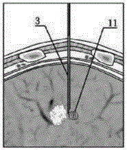
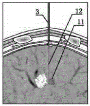
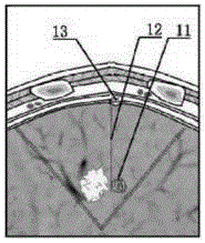
[0040] refer to Figure 1~Figure 13 , one aspect of the present invention relates to a temporary implanted positioning marker 1 for precise localization of small space-occupying lesions in the lung during thoracoscopic surgery, which is removable and includes a firm anchor that can be provided in the lung tissue A fixed head end 11, a tail end 13 that can provide firm anchoring on the visceral pleura on the surface of the lung, and a middle section 12 arranged between the head end 11 and the tail end 13. The length of the temporary implanted positioning marker 1 has various specifications, mainly because the length of the middle section 12 is different, so the temporary implanted positioning marker with an appropriate length can be selected according to the distance between the space-occupying lesion and the pleural surface 1 for surgery.

[0041] In order to facilitate the understanding of the specific structure of the temporary implant positioning marker 1 of the present in...


PUM

PropertyMeasurementUnit
Outer diameteraaaaaaaaaa
Lengthaaaaaaaaaa

Abstract

The invention discloses a temporarily-implanted positioning marker fir positioning a tiny space occupying lesion inside the lung. The temporarily-implanted positioning marker comprises a head end, a tail end and a middle section, wherein the head end can provide firm anchoring inside the lung tissue the tail end can provide firm anchoring on the visceral pleurae on the surface of the lung, and the middle section is arranged between the head end and the tail end and the proper length of the middle section can be selected according to the distance between the space occupying lesion and the adjacent visceral pleura faces. Due to the preforming structures of the head end and the tail end of the temporarily-implanted positioning marker, the temporarily-implanted positioning marker can be firmly anchored inside the lung tissue, meanwhile the temporarily-implanted positioning marker is slender in structure, soft in texture and easy to bend inside the lung tissue after being implanted, serious damage to the lung tissue cannot be caused in the implanting process and after the implanting process, the tiny space occupying lesion inside the lung tissue can be conveniently found along the implanted marker, and the temporarily-implanted positioning marker is quite suitable for accurately positioning the tiny space occupying lesion inside the lung tissue in a thoracoscope operation.

Description

technical field [0001] The present invention relates to a medical device and its technology, in particular to a temporary implant positioning marker for precise positioning of tiny space-occupying lesions in the lungs during thoracoscopic surgery and a manufacturing method thereof, as well as a temporary Implantation positioning markers are accurately delivered to the delivery device at the designated location in the lung and the positioning system used during the implantation process. Background technique [0002] Lung cancer is the most common cause of death in industrialized countries. The prognosis of lung cancer is affected by many factors, the most important of which is the tumor stage at the time of patient presentation. Peripheral lung cancer patients with a diameter less than 30 mm are the best indications for surgical treatment, and the 5-year survival rate after surgery is as high as 60% to 80%. If the diameter of the space-occupying lesion in the patient's lung...

Claims


Application Information

Patent Timeline
IPC IPC(8): A61B19/00
Inventor 金龙
Owner 常州爱康臻医疗科技有限公司
Learn More