Single-cycle heat pump power generation device
A power generation device and single-cycle technology, which is applied to steam engine devices, machines/engines, mechanical equipment, etc., to achieve the effects of mitigating the increasingly serious environmental pollution, high energy conversion efficiency, and mitigating the aggravation of the energy crisis
- Summary
- Abstract
- Description
- Claims
- Application Information
AI Technical Summary
Problems solved by technology
Method used
Image

Examples
Embodiment Construction
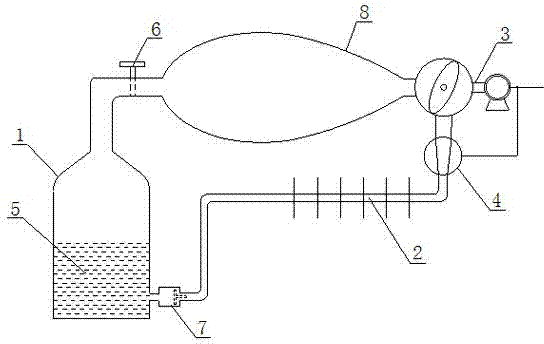
[0014] A single-cycle heat pump power generation device, such as figure 1 As shown, it includes an evaporator 1, a condenser 2, a turbine generator set 3 and a compressor 4. The evaporator 1 stores a liquid refrigerant 5 and forms an air chamber. The gas outlet of the evaporator 1 is installed with a The pipeline of the sealing valve 6 is connected to the turbine inlet of the turbogenerator set 3, the turbine exhaust port of the turbogenerator set 3 is connected to the inlet of the condenser 2 through the compressor 4, and the outlet of the condenser 2 is installed with a one-way throttling valve. The pipeline of the valve 7 is connected with the liquid inlet of the evaporator 1 , and the power line of the compressor 4 is electrically connected with the power output line of the turbine generator set 3 . The outer wall of the evaporator 1 is covered with a heat absorbing film layer. A gas decompression acceleration container 8 with a fluid-type inner cavity is arranged between...
PUM
 Abstract
Description
Claims
Application Information
PatSnap Eureka turns technology decisions into work you can execute. Powered by our Innovation Knowledge Graph, it runs expert workflows across engineering, life sciences, materials and intellectual property. Get your review-ready output in minutes.


