Liquid crystal display

A liquid crystal display and liquid crystal display panel technology, applied in the direction of instruments, nonlinear optics, optics, etc., can solve the problem of adjacent pixel pollution

Inactive Publication Date: 2014-06-25
RADIANT OPTO ELECTRONICS
View PDF6 Cites 9 Cited by
  • Summary
  • Abstract
  • Description
  • Claims
  • Application Information

AI Technical Summary

Problems solved by technology

In this way, if figure 2 As shown by the dotted boxes 228 and 230 of , after the red light and green light pass through the liquid crystal layer 220, they may irradiate adjacent pixels, causing adjacent pixels to be polluted by red light or green light

Method used


Image

  • Liquid crystal display
  • Liquid crystal display
  • Liquid crystal display

Examples


Embodiment Construction

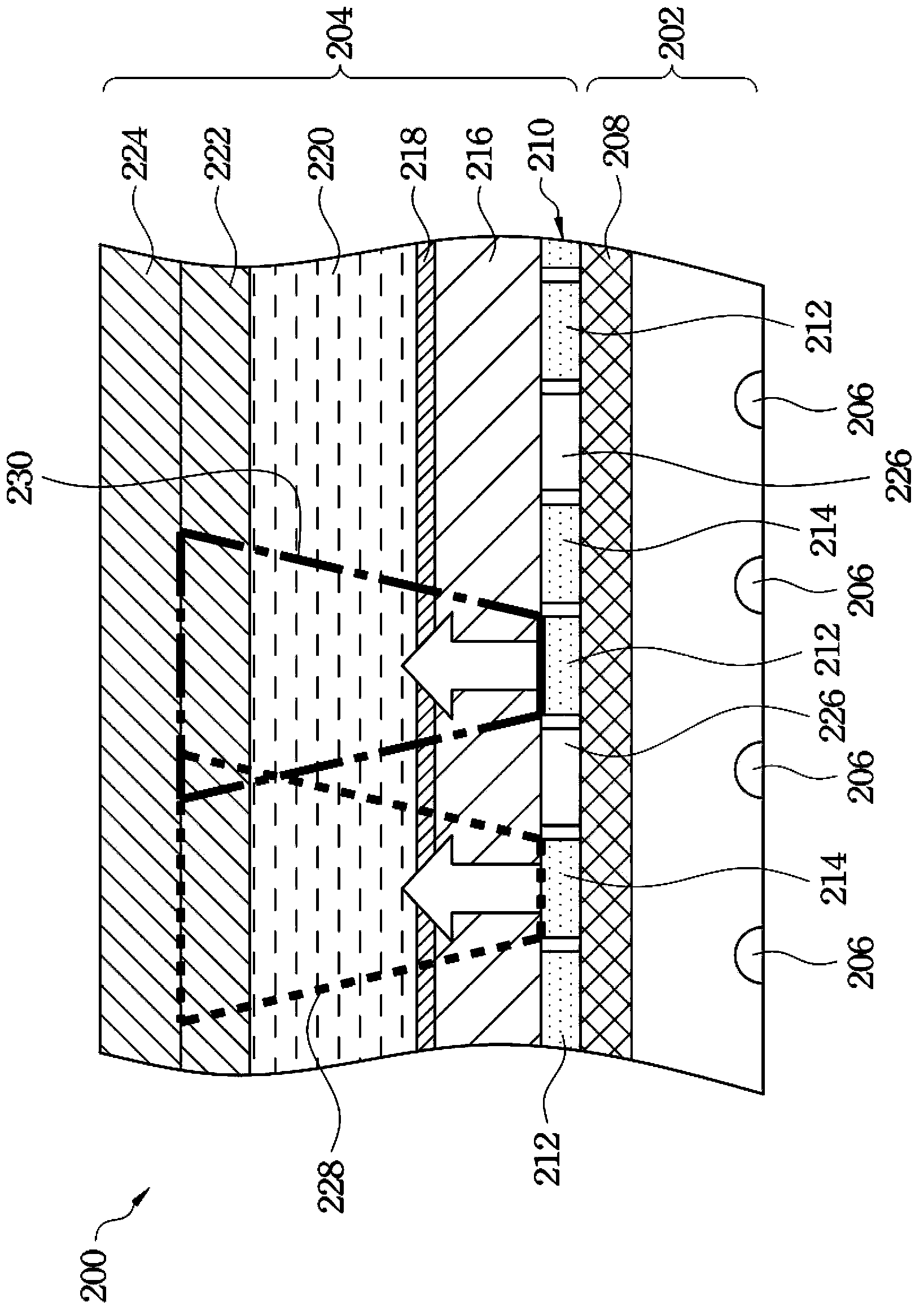
[0037] Please refer again figure 2, in order to prevent adjacent pixels of the liquid crystal display 200 from being polluted by red light or green light, the inventor proposes a solution of disposing a color filter (not shown) above the liquid crystal layer 220 . Use this color filter to filter out unnecessary colored light in pixels. However, the inventor believes that under the structure of the liquid crystal display 200, the thickness of the phosphor layer 210 should not be large, and there will be spaces between the particles of the phosphor, so that the blue light is likely to be emitted from the phosphor. These spaces of layer 210 are scattered out. Therefore, when the blue light passing through the red phosphor region 212 and the green phosphor region 214 is not completely absorbed, but part of the blue light passes through the phosphor layer 210 and exits, the red phosphor region 212 and the green phosphor The color of the light generated after the region 214 is no...


PUM


Abstract

A liquid crystal display is described, which includes a backlight module and a liquid crystal display panel. The backlight module includes a light guide plate and a plurality of blue light-emitting diodes adjacent to the light guide plate. The liquid crystal display panel is disposed above the backlight module. The liquid crystal display panel includes a first transparent substrate, a first electrode, a liquid crystal layer, a phosphor powder layer, a color filter, a second electrode and a second transparent substrate stacked above the light guide plate in sequence. The phosphor powder layer includes a plurality of green phosphor powder regions and red phosphor powder regions. The color filter is adjacent to the phosphor powder layer. The color filter includes a plurality of green color filter regions and red color filter regions respectively and correspondingly located, on the green phosphor powder regions and the red phosphor powder regions.

Description

technical field [0001] The present invention relates to a flat panel display device, and more particularly to a liquid crystal display (LCD). Background technique [0002] Please refer to figure 1 , which is a schematic diagram of a conventional liquid crystal display device. The liquid crystal display 100 mainly includes a backlight module 102 and a liquid crystal display panel 104 . The backlight module 102 is disposed on the back of the liquid crystal display panel 104 to provide a light source for the liquid crystal display panel 104 . The backlight module 102 generally includes a light guide plate 106 and a plurality of light emitting diodes (LEDs) 120 . The light emitting diodes 120 are disposed beside the side of the light guide plate 106 . Each LED 120 includes a LED die 108 and a phosphor layer 110 , wherein the phosphor layer 110 covers the LED die 108 . [0003] The liquid crystal display panel 104 mainly includes a first glass substrate 112 , a liquid crysta...

Claims


Application Information

Patent Timeline
Patent Type & Authority Applications(China)
IPC IPC(8): G02F1/13357G02F1/1335
CPCG02F1/133603G02F1/133514G02F1/133617
Inventor 吴易座
Owner RADIANT OPTO ELECTRONICS
Why Eureka
Try Eureka