Correction method for illumination uniformity of exposure system of lithography machine

A technology of an exposure system and a correction method, which is applied to microlithography exposure equipment, photolithographic process exposure devices, etc., can solve problems such as unfavorable long-term stability of the exposure system, unfavorable system integration, decrease in transmittance, etc., so as to improve the overall transmittance. efficiency, reduced complexity, and strong adaptability

Active Publication Date: 2016-02-10
SHANGHAI INST OF OPTICS & FINE MECHANICS CHINESE ACAD OF SCI
View PDF6 Cites 0 Cited by
  • Summary
  • Abstract
  • Description
  • Claims
  • Application Information

AI Technical Summary

Problems solved by technology

[0004] 1) Both methods will cause a certain energy loss. Both methods attenuate the part with strong light intensity in the illumination area to achieve uniformity correction, which will cause a decrease in the overall energy of the system and affect the productivity of the lithography machine;
[0005] 2) The optical system is required to have a longer optical working distance, which increases the difficulty of optical design;
[0006] 3) Additional optical and mechanical components need to be placed, which increases the complexity of the system. The uniformity correction device contains moving parts with a large amount of movement, which requires more complex motion and control mechanisms, which is not conducive to system integration;
[0007] 4) Both of these two methods contain shading elements, and the scattering of the light beam by the elements will increase the system noise, which is not conducive to the long-term stability of the exposure system
When this method compensates for a system with poor uniformity, it will cause a sharp drop in transmittance, resulting in a decrease in the yield of the lithography machine

Method used


Image

  • Correction method for illumination uniformity of exposure system of lithography machine
  • Correction method for illumination uniformity of exposure system of lithography machine
  • Correction method for illumination uniformity of exposure system of lithography machine

Examples


Embodiment Construction

[0028] The present invention will be further described below in conjunction with accompanying drawings and examples, but the protection scope of the present invention should not be limited thereby.

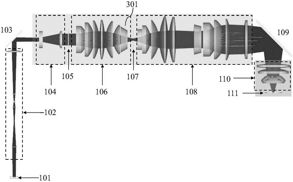
[0029] see first figure 1 , figure 1 It is a local light path diagram of the exposure system of the lithography machine, including the local light path from the diffractive optical element to the mask plate, and is the main optical system constituting the illumination system in the exposure system of the lithography machine, including the diffractive optical element 101, the zoom collimator lens group in turn 102 , first reflector 103 , conical mirror group 104 , microlens array 105 , condenser lens group 106 , scanning slit 107 , front group of illuminating mirror group 108 , second reflecting mirror 109 and rear group of illuminating mirror group 110 . The rectangular illumination spot generated by the illumination system is irradiated on the mask 111 , and the pattern of the m...


PUM


Abstract

The invention discloses a correcting method of lighting uniformity of a photoetching machine exposure system. The method comprises the following steps of moving the last lens of a collecting lens group along an optical axis direction, and thus realizing the regulation of relative light intensity the edge position and the center position of a rectangle lighting light spot. The correcting method disclosed by the invention has the advantages that an optical element does not need to be additionally arranged, and the correction of the lighting uniformity is realized by simply moving the existing optical element in the photoetching machine exposure system. The method has the characteristics that the operation is convenient, and the light intensity attenuation is not caused; the correcting method is suitable for the photoetching machine exposure system of any ultraviolet light wave band.

Description

technical field [0001] The invention relates to photolithography equipment, in particular to a method for correcting illumination uniformity of an exposure system of a photolithography machine. Background technique [0002] In the exposure system of an advanced lithography machine, in order to ensure the consistency and uniformity of the exposure lines, the illumination spot irradiated on the mask plate is required to have very high uniformity during one exposure process. Especially in step and scan lithography machines, the integral non-uniformity along the non-scanning direction (defined as the X direction) is usually required to be less than 0.5%. The micro-lens array with precise surface shape is used to decompose and re-integrate the light beam to achieve high uniformity of the illumination spot. However, due to the different positions of the light on different illumination spots passing through the lens during the beam propagation process, the absorption of light on d...

Claims


Application Information

Patent Timeline
Patent Type & Authority Patents(China)
IPC IPC(8): G03F7/20
Inventor 朱菁黄惠杰曾爱军杨宝喜陈明李璟王健魏张帆张方
Owner SHANGHAI INST OF OPTICS & FINE MECHANICS CHINESE ACAD OF SCI
Why Eureka
Try Eureka