satellite navigation antenna

A satellite navigation antenna and antenna technology, applied in the field of satellite navigation systems, can solve the problems of not being able to ensure stability, unidirectionality, and small bandwidth at the same time, achieve good mechanical characteristics and temperature characteristics, increase receiving bandwidth, and increase the effect of inductance

Active Publication Date: 2016-08-31
BEIJING METABTAR RADAR
View PDF5 Cites 0 Cited by
  • Summary
  • Abstract
  • Description
  • Claims
  • Application Information

AI Technical Summary

Problems solved by technology

However, the inventors have found through research that the traditional microstrip patch antenna and dipole antenna not only have a small bandwidth, but also cannot guarantee good stability and unidirectionality at the same time

Method used


Image

  • satellite navigation antenna
  • satellite navigation antenna
  • satellite navigation antenna

Examples


Embodiment Construction

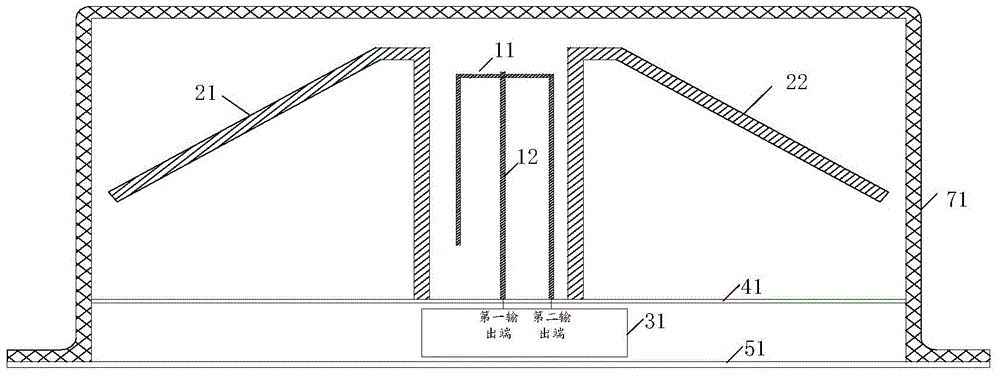
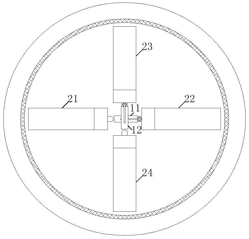
[0048] see figure 1 and figure 2, the present invention provides a specific embodiment of the satellite navigation antenna, this embodiment specifically includes: 2 feeding probes, 2 pairs of dipoles, 3db bridge 31 , first reflector 41 and second reflector 51 . Among them, the two feeding probes are feeding probe 11 and feeding probe 12 respectively. Wherein, each pair of dipoles includes 2 dipoles, and the 2 pairs of dipoles are dipole 21 , dipole 22 , dipole 23 and dipole 24 . The dipole 21 and the dipole 22 are a pair, and the dipole 23 and the dipole 24 are another pair.

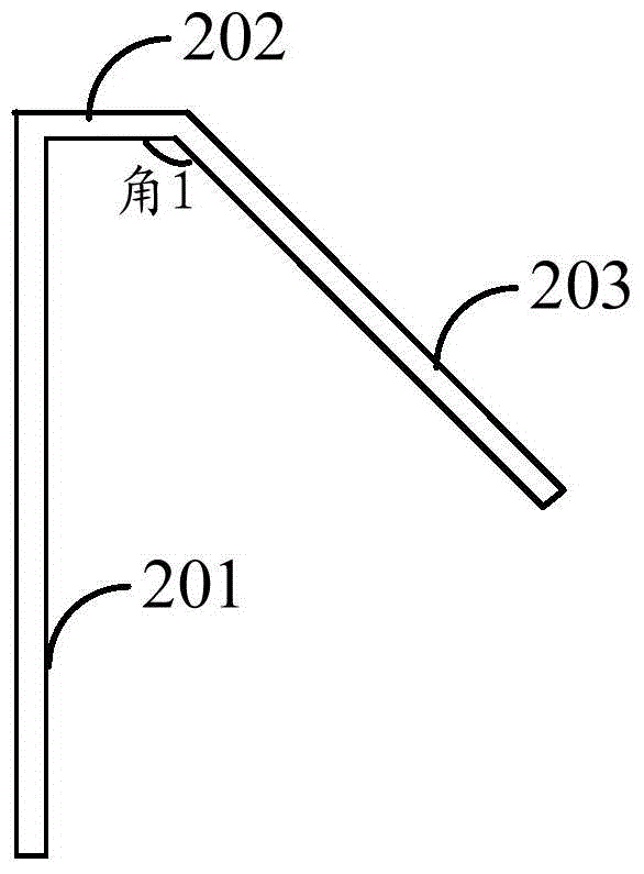
[0049] like image 3 As shown, any dipole in this embodiment includes three parts: a first part 201, a second part 202 and a third part 203; wherein, the first end of the first part 201 is connected to the first end of the second part 202, And the first part 201 and the second part 202 are perpendicular to each other, the second end of the second part 202 is connected to the first end of the third p...


PUM


Abstract

The invention provides a satellite navigation antenna which comprises two pairs of dipoles, two feed probes, one 3db bridge and two reflective plates. One pair of the two pairs of the dipoles is arranged symmetrically along a straight line and located on a first plane, the other pair of the dipoles is arranged symmetrically along the same straight line and located on a second plane, the first plane is perpendicular to the second plane, and the two pairs of the dipoles are arranged in a cross shape when people look down at the antenna. The two feed probes are located in the middle of the two pairs of the dipoles, namely the center of the cross shape. Each dipole comprises three parts, the angle between the second part and the third part is 145 degrees, wherein the first part is a magnetic dipole, and the second part and the third part are electric dipoles, so that the combination of the electric dipole and the electric dipoles is achieved, the combined dipole is simulated through a specific feed probe, bandwidths and beams of the navigation antenna are broaden, and good stability and unidirectionality of a directivity diagram in the working frequency band are remained.

Description

technical field [0001] The invention relates to the field of satellite navigation systems, in particular to a satellite navigation antenna. Background technique [0002] Nowadays, the development of satellite navigation systems is in full swing. The satellite navigation systems currently in operation and under construction include the GPS (global position system, Global Positioning System) of the United States, the "Beidou" second-generation system of China, the Galileo (Galileo) system of Europe and Russia's GLONASS (GLONASS) system and so on. [0003] Among them, as the most front-end component in the satellite navigation system, the performance of the satellite navigation antenna directly affects the communication quality of the whole system. However, the inventors have found through research that the traditional microstrip patch antenna and dipole antenna not only have a small bandwidth, but also cannot guarantee good stability and unidirectionality at the same time. ...

Claims


Application Information

Patent Timeline
Patent Type & Authority Patents(China)
IPC IPC(8): H01Q1/36
Inventor 左申正张建云王恩成刘依楠
Owner BEIJING METABTAR RADAR
Why Eureka
Try Eureka