Optical fiber coupling vertical-cavity surface emitting laser with power monitoring function

A vertical cavity surface emission, fiber coupling technology, applied in lasers, laser parts, semiconductor lasers, etc., can solve problems such as inconvenience in practical use, the chip does not integrate a power detection chip, affecting high-speed modulation performance, etc., to improve the operating temperature range. , the effect of increasing temperature stability and structural stability, increasing temperature stability and reliability

Inactive Publication Date: 2014-06-25
SHANGHAI INST OF OPTICS & FINE MECHANICS CHINESE ACAD OF SCI
View PDF6 Cites 19 Cited by
  • Summary
  • Abstract
  • Description
  • Claims
  • Application Information

AI Technical Summary

Problems solved by technology

It can also be controlled by integrating the power detection chip on the vertical cavity surface emitting laser chip. Although the degree of integration is high, the performance of the vertical cavity surface emitting laser will affect the power detection chip to varying degrees due to the integration on the same substrate. At the same time, the detection chip will also affect its high-speed modulation performance, and most of the current high-speed or high-power vertical cavity surface emitting lasers do not have integrated power detection chips on the chip, which brings inconvenience to actual use

Method used


Image

  • Optical fiber coupling vertical-cavity surface emitting laser with power monitoring function
  • Optical fiber coupling vertical-cavity surface emitting laser with power monitoring function

Examples


Embodiment Construction

[0015] The present invention will be further described below in conjunction with the embodiments and accompanying drawings.

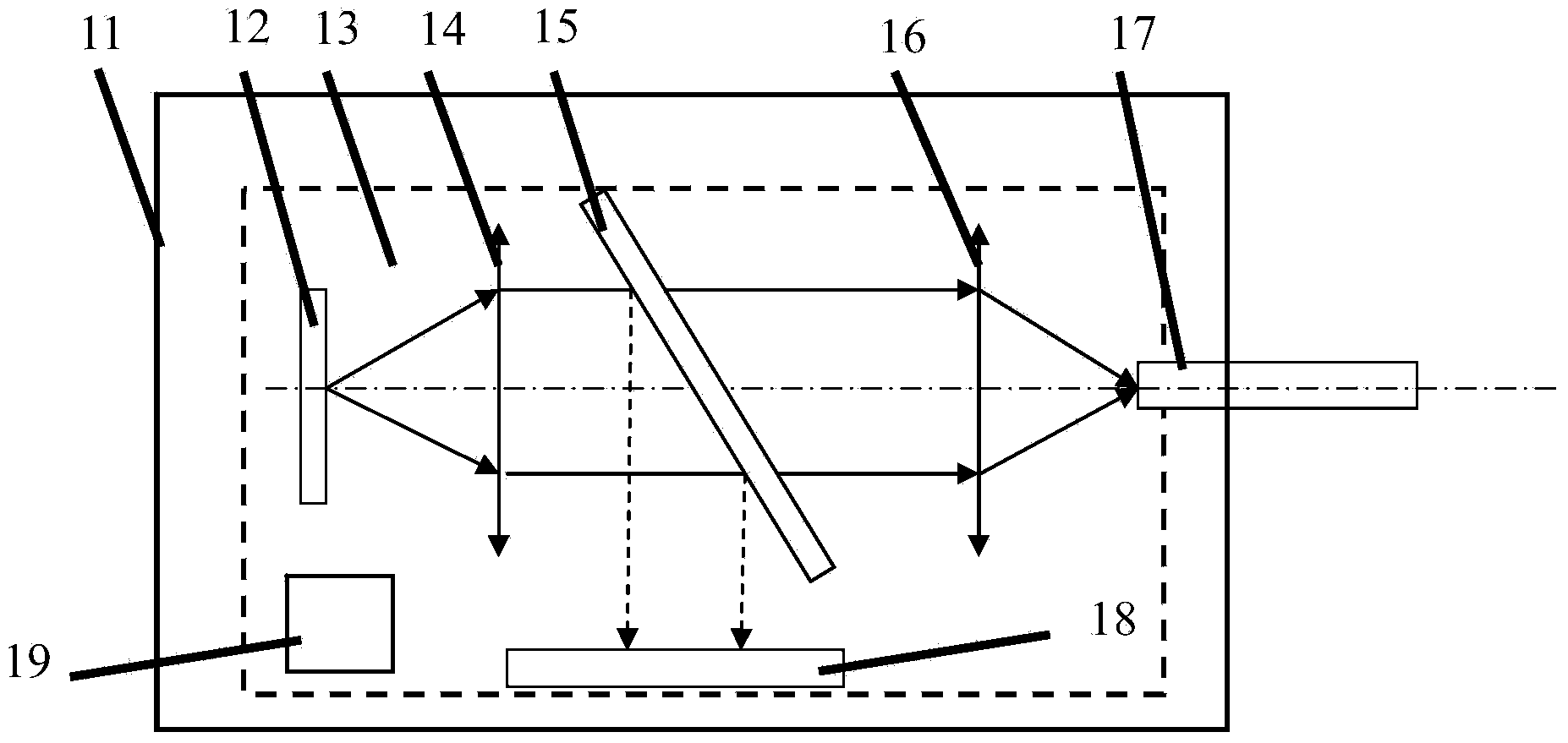
[0016] see first figure 1 , figure 1 It is a schematic structural diagram of Embodiment 1 of the present invention; this embodiment has a fiber-coupled vertical cavity surface emitting laser with power monitoring, including a laser housing 11, a vertical cavity surface emitting laser 12, a semiconductor cooler 13, a collimating lens 14, and a beam splitter 15. Coupling lens 16, coupling fiber assembly 17, power detector 18 and thermistor 19. The beam splitter 15 is a transmission type, the transmitted light is greater than the reflected light (reflected light accounts for about 1-2%), the semiconductor cooler 13 is welded to the inner bottom surface of the laser tube shell 11 by high temperature solder, and the vertical cavity surface emitting laser 12 Fixed on the upper surface of semiconductor refrigerator 13 or excessive heat sink by high-temperatu...


PUM


Abstract

Provided is an optical fiber coupling vertical-cavity surface emitting laser with a power monitoring function. The laser comprises a laser shell, a semiconductor refrigerator, a vertical-cavity surface emitting laser body, a collimating lens, a lighting distributing plate, a coupling lens, a detector and an optical fiber assembly. The laser has the advantages of having the power monitoring function, being high in temperature stability and reliability, truly achieving all-metal hermetic sealing and the like.

Description

technical field [0001] The invention relates to a fiber-coupled laser, in particular to a fiber-coupled vertical-cavity surface-emitting laser with power monitoring. Background technique [0002] Compared with the side-emitting FP cavity laser, the vertical cavity surface emitting laser has the advantages of extremely low threshold current, low noise, good dynamic single-mode operation, circular output spot, and easy coupling with optical fiber. It has broad application prospects in interconnection, gas detection, optical storage, etc. Due to its small divergence angle and circularly symmetrical spot, the coupling efficiency with the fiber is greatly improved, and the coupling efficiency can be greater than 90%, which is much higher than that of the FP cavity side-emitting laser. Due to the characteristics of the vertical cavity surface emitting laser structure, it is difficult to monitor the chip power inside the laser module, so the fiber coupled output vertical cavity su...

Claims


Application Information

Patent Timeline
Patent Type & Authority Applications(China)
IPC IPC(8): H01S5/183G02B6/42
Inventor 辛国锋皮浩洋孙广伟耿健新刘庆琰蔡海文瞿荣辉
Owner SHANGHAI INST OF OPTICS & FINE MECHANICS CHINESE ACAD OF SCI
Why Eureka
Try Eureka