Data-driven optimization of event acceptance/rejection logic

A technology of event and dynamic adjustment, applied in the field of nuclear medicine imaging, can solve the problem of inability to change, and achieve the effect of image quality improvement

Inactive Publication Date: 2014-06-25
KONINKLJIJKE PHILIPS NV
View PDF11 Cites 11 Cited by
  • Summary
  • Abstract
  • Description
  • Claims
  • Application Information

AI Technical Summary

Problems solved by technology

The hardware parameters used to determine coincidence events are typ

Method used


Image

  • Data-driven optimization of event acceptance/rejection logic
  • Data-driven optimization of event acceptance/rejection logic
  • Data-driven optimization of event acceptance/rejection logic

Examples


Embodiment Construction

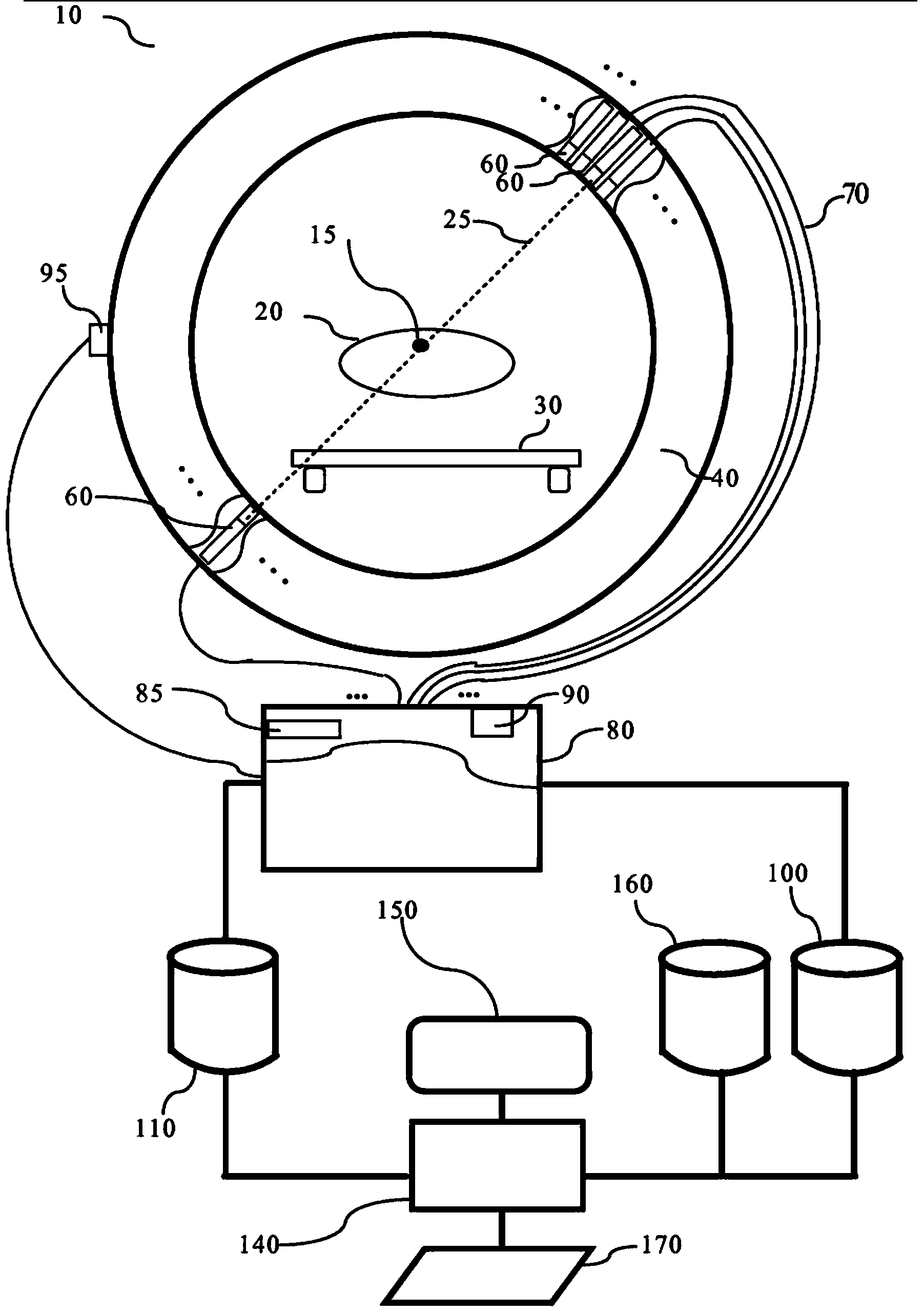
[0028] refer to figure 1 , the PET scanner 10 detects positron emission events. The location of the annihilation event 15 occurs within the subject, target organ or region of interest 20 . The subject is placed on an examination table 30 which moves past a detector array 40 . Detector array 40 is typically annular within gantry 30 with longitudinally extending rows of detectors 60 . Detector 60 receives the gamma photons and emits an electrical pulse on wired circuit 70 upon impact of the gamma photons. Examples of detectors are scintillator crystals connected with photomultipliers, photodiodes, silicon photomultipliers (SiPMs), etc. The amplitude of the pulse reflects the energy of the received photon. Using an analog-to-digital converter (if the photodetector is not digital), the clock circuit adds a time stamp, and the detector circuit adds the identity or position of the detecting detector to form digital data for each detected event Bag. The wired circuit 70 connect...


PUM


Abstract

In Positron Emission Tomography, a time window (260) and an energy window (225) are dynamically adjusted, based on an attenuation map, count rate, clinical application, discrimination tailoring, and/or offline discrimination tailoring. Detected radiation events are filtered using the dynamically adjusted energy and time windows into scattered events, random events, and true events. The true events are input to image reconstruction, correction, and error analysis.

Description

technical field [0001] The present application relates to nuclear medicine imaging, positron emission tomography (PET), single photon emission computed tomography (SPECT), and in particular to the determination of events used to reconstruct PET images. Background technique [0002] PET nuclear medicine involves the introduction of radiopharmaceuticals into the subject. The radiopharmaceuticals are targeted to specific regions or organs of interest through metabolic processes. The radiopharmaceutical decays with a relatively short half-life. The fundamental process for image formation is a decay event that causes the emission of a positron. The positrons travel a short distance before hitting an electron. When the positron hits the electron, an annihilation event occurs. The annihilation event is marked by the emission of two gamma photons of energy 511 keV traveling in 180° opposite directions. The path that photons travel in the opposite direction is called the line of...

Claims


Application Information

Patent Timeline
IPC IPC(8): G01T1/29
CPCA61B6/547A61B6/5294A61B6/481A61B6/469G01T1/2985A61K2123/00A61B6/5205A61K51/00A61B6/544A61B6/0407A61K2121/00A61B6/037
Inventor S·普雷弗尔哈尔E·S·汉西斯J·S·维纳J·布雷多诺D·索厄德斯-埃梅德L·邵
Owner KONINKLJIJKE PHILIPS NV
Why Eureka
Try Eureka