Low-energy-consumption purification device

A purification device and low-energy-consumption technology, applied in separation devices, chemical instruments and methods, and the use of liquid separation agents, can solve problems such as condensation and separation of volatile organic compounds, and achieve the goal of expanding the range of treatable temperatures and improving the efficiency of adsorption treatment Effect

Inactive Publication Date: 2014-07-02
CHENG YUAN ENVIRONMENTAL TECH
View PDF5 Cites 1 Cited by
  • Summary
  • Abstract
  • Description
  • Claims
  • Application Information

AI Technical Summary

Problems solved by technology

[0003] Second, such as " figure 1 As shown in ", the existing condensing device used to separate water-soluble volatile organic compounds from the air stream to be purified is usually provided with a condenser 11 inside an air flow channel 10 to be purified, so that the air stream to be purified passing through the condenser 11 The temperature drops below the dew point temperature, and the water-soluble volatile organic compounds contained in the gas stream to be purified are condensed and separated by using the condensation of the volatile organic compounds themselves and the adsorption of condensed water droplets; then, at the downstream end of the condenser 11 A demister 12 or a second condenser (not shown) are set to allow the volatile organic compounds and water vapor with smaller particle sizes to grow and be captured for separation or secondary condensation; however, the condenser 11 is usually combined with ice The water machine 13 is connected, and the ice water machine is a heat exchanger with high energy consumption, and once the temperature of the airflow to be purified is higher than the working temperature of the condenser 11 (the outlet water temperature of the connected ice water machine 13 can be used as a reference temperature) Most of the time, the ice water machine of general specifications cannot provide sufficient condensation effect, and the condenser 11 cannot condense and separate the volatile organic compounds. In addition, when the ambient temperature or relative humidity is low, the operating temperature of the condenser 11 When it is higher than the dew point temperature of the air stream to be purified, a chiller with a higher specification must be used to produce condensation

Method used


Image

  • Low-energy-consumption purification device
  • Low-energy-consumption purification device
  • Low-energy-consumption purification device

Examples


Embodiment Construction

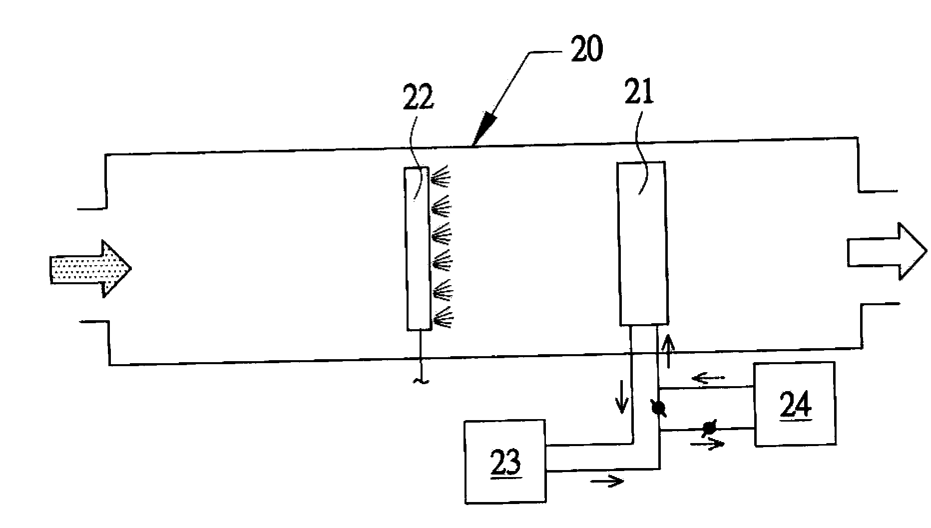
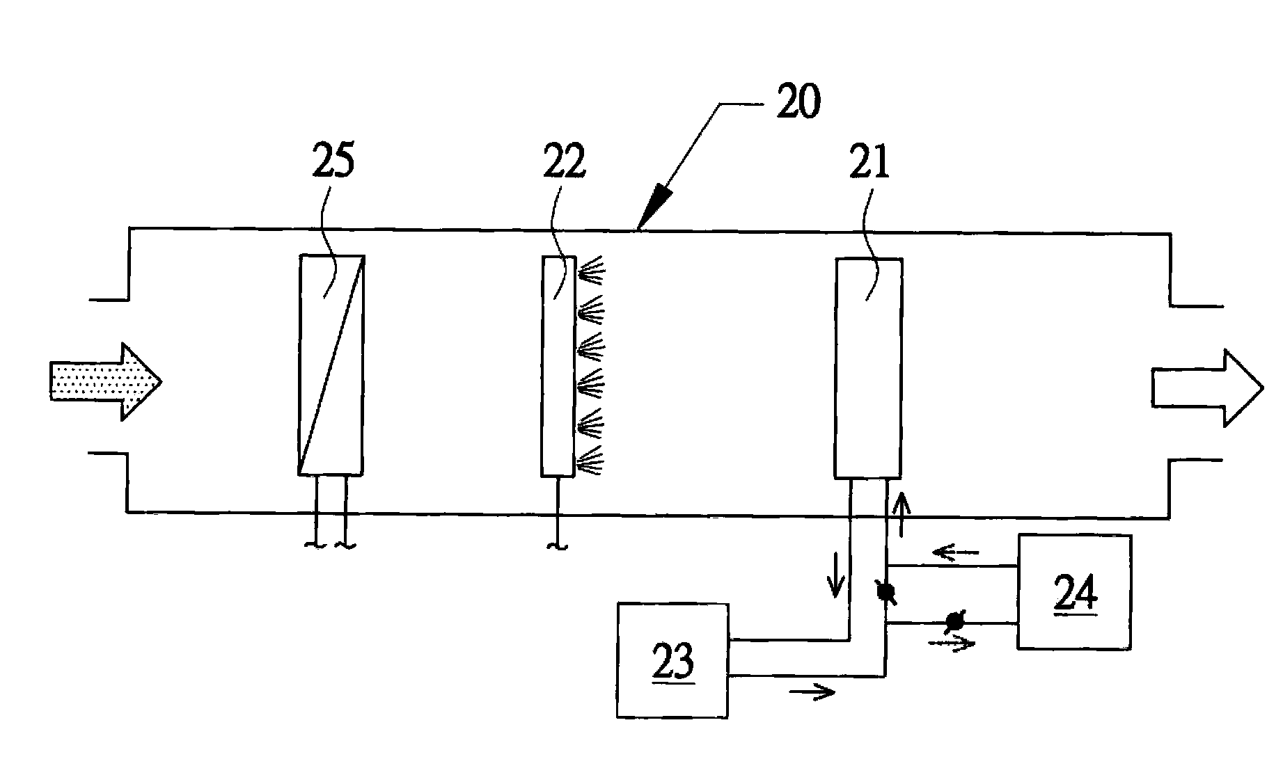
[0028] First, see the " figure 2 As shown in ", the first embodiment of the low-energy purification device of the present invention includes: a humidifier 22, which is arranged inside a to-be-purified airflow channel 20, and is used to increase the humidity by spraying water mist on the passing airflow to be purified. In addition to increasing the dew point temperature, it can also be cooled and used to remove substances to be purified (volatile organic compounds or suspended particles); a condenser 21 is arranged inside the airflow channel 20 to be purified and is located at the downstream end of the humidifier 22 for Condensing the humidified gas stream to be purified to produce a condensate containing substances to be purified (volatile organic compounds or suspended particles); and a heat exchanger 23 connected to the condenser 21 to allow the condenser 21 to achieve the expected condensation temperature, and the heat exchanger 23 is a cooling water tower, and even furthe...


PUM


Abstract

A low energy-consumption purification device comprises a humidifier (22) arranged inside an unpurified airflow passage (20) to spray water mist all over the unpurified airflow for increasing humidity thereof; a condenser (21) arranged inside the unpurified airflow passage (20) and located at a downstream end of the humidifier (22) to condense the unpurified airflow into condensate contained substances requiring purification; an air temperature controller (25) arranged inside the unpurified airflow passage (20) and located at an upstream end of the humidifier (22) for warming or cooling the unpurified airflow in the air temperature controller (25); and a first heat exchanger (23) connected to the condenser (21) to achieve a desired condensing temperature. The present invention is able to enhance a performance of an adsorption treatment for unpurified substances and provide the effect of expanding the rage of the treatment temperature.

Description

technical field [0001] The present invention relates to a low energy consumption purification device, especially a kind of spraying water mist to increase the humidity of the airflow to be purified to increase the dew point temperature, increase the temperature difference between the dew point temperature of the airflow to be purified and the working temperature of the condenser, and then use low Energy-consuming cooling towers replace conventional high-energy-consuming chillers for condensation treatment. Background technique [0002] Organic solvents, which are widely used in life and production, easily volatilize into gases at room temperature, so they are also called Volatile Organic Compounds (VOCs). Most of the VOCs are toxic to the human body and must be purified. However, if the air stream to be purified produced by the process contains water-soluble volatile organic compounds with high boiling point and low vapor pressure, it is usually separated by a condensing dev...

Claims


Application Information

Patent Timeline
IPC IPC(8): B01D53/00B01D5/00
CPCB01D53/002B01D47/05B01D47/06B01D53/1487B01D2257/708B01D2247/08
Inventor 林易成
Owner CHENG YUAN ENVIRONMENTAL TECH
Why Eureka
Try Eureka