A kind of pulverized coal fiber separator

A fiber separation and pulverized coal technology, which is applied in the direction of solid separation, classification, and separation of solids from solids with airflow, can solve the problems of increasing the labor intensity of maintenance workers, affecting the normal operation of the system, and affecting the flux of pulverized coal. Achieve the effect of simple structure, prevent bridging, and improve service life

Inactive Publication Date: 2016-04-06
TIANJIN WEICHER TECH
View PDF7 Cites 0 Cited by
  • Summary
  • Abstract
  • Description
  • Claims
  • Application Information

AI Technical Summary

Problems solved by technology

[0004] The fiber separator in the prior art has the following problems: the equipment is a vertical structure, the coal powder flows from top to bottom, while the comb filter mechanism rotates horizontally, and the comb bars are arranged radially, it is difficult to fully contact with the coal powder, and the purification efficiency is relatively low. Low; in actual operation, because the fibers are only wound on the barbs without separation treatment, the surface of the barbs is smooth, and after the long fibers that have been carded slide to the roots of the barbs, due to the impact of coal powder and the multiple rotation structures function, it is easy to separate from the thorns and re-mixed into the coal powder, the fibers are always present on the coal powder channel, the agglomerated fibers cause the grid to often block and affect the coal powder flux, and the blockage can easily spread to the entire cross-section, Coal powder is piled up on the grille, crushing the driving device, causing the entire equipment to stop, and the grille is covered with the entire section. It increases the labor intensity of maintenance workers and affects the normal operation of the system

Method used


Image

  • A kind of pulverized coal fiber separator
  • A kind of pulverized coal fiber separator
  • A kind of pulverized coal fiber separator

Examples


Embodiment Construction

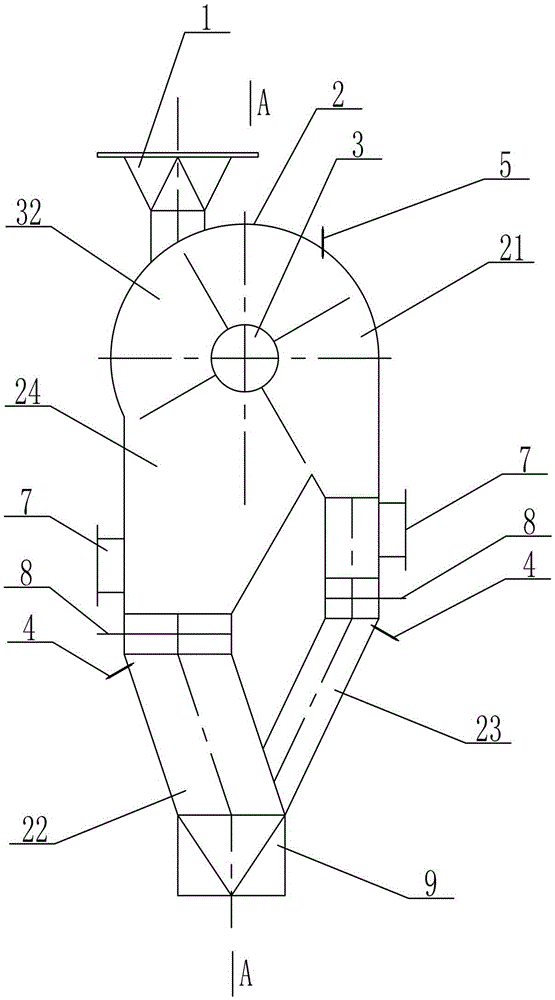
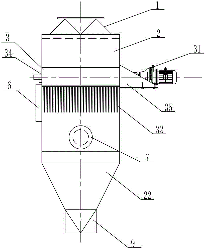
[0017] See attached figure 1 ~attached figure 2 , the present invention consists of a comb filter mechanism 3 arranged on the shell 2, the top of the shell 2 is provided with a feed port 1, and the bottom of the shell 2 is provided with a discharge port 9; the shell 2 is composed of a horizontal cylinder 21 The connected pulverized coal pipe 22 and the fiber pipe 23 are formed. The pulverized coal pipe 22 and the fiber pipe 23 are connected with the cylinder body 21 by the inclined cone 24 of the bifurcated structure. The discharge port 9 at the bottom of the shell 2 is connected with the pulverized coal pipe 22 and The fiber tube 23 is connected, and the feed port 1 at the top of the shell 2 is arranged on the cylinder 21; the pulverized coal tube 22 and the upper part of the fiber tube 23 are provided with a filter screen 8 with a drawer structure, and the filter screen 8 is connected to the pulverized coal tube 22. It is slidingly connected with the fiber tube 23; the com...


PUM


Abstract

The invention discloses a pulverized coal fiber separator which comprises a shell and a combing and filtering mechanism. The pulverized coal fiber separator is characterized in that the shell is composed of a pulverized coal pipe and a fiber pipe which are connected by a horizontal barrel, the pulverized coal pipe and the fiber pipe are connected with the barrel by an oblique cone of a crotch structure, a discharging port at the bottom of the shell is connected with the pulverized coal pipe and the fiber pipe, a filtering net of a drawer structure is arranged on the upper portions of the pulverized coal pipe and the fiber pipe, the combing and filtering mechanism is composed of a driving device and a thorn combing roller, the thorn combing roller is mounted in the barrel in a sleeved manner by two shaft seats arranged on the barrel, and the driving device is fixedly arranged outside the barrel by a support to be connected with the thorn combing roller. Compared with the prior art, the pulverized coal fiber separator has the advantages of being simple in structure, strong in fiber capturing capability, high in pulverized coal purifying efficiency, reliable in working and long in service life, and the filtering net is less prone to being blocked.

Description

technical field [0001] The invention relates to separation screen equipment, in particular to a pulverized coal fiber separator which is collected by combs and filter screens. Background technique [0002] In the coal gasification process, many processes need to grind the raw coal into pulverized coal, and then send it to the gasifier through the burner for gasification. Due to reasons such as raw coal and transportation and storage, the pulverized coal is mixed with fibers of different lengths, which are easy to block the pneumatic conveying pipeline or bond at the burner, which affects the long-term stable operation of the system. Adding fiber separator equipment to the system can effectively separate fibers and improve the purity of pulverized coal. [0003] At present, the comb filter mechanism of the pulverized coal fiber separator generally adopts a double-layer separation structure of comb comb and grid filter screen. The grid is a combined circular sieve plate, whi...

Claims


Application Information

Patent Timeline
Patent Type & Authority Patents(China)
IPC IPC(8): B07B9/00B07B13/00B07B7/06B07B1/04B07B1/55
Inventor 张小研毛智强江海宝
Owner TIANJIN WEICHER TECH
Why Eureka
Try Eureka