Draining pump

A technology for drainage pumps and water pump casings, applied to pumps, pump devices, pump components, etc., can solve the problems of reduced blade efficiency and low workmanship efficiency, and achieve the effects of ensuring long life, suppressing noise, and improving performance

Active Publication Date: 2014-07-02
CHANGZHOU LEILI MOTOR SCI & TECH
View PDF10 Cites 5 Cited by
  • Summary
  • Abstract
  • Description
  • Claims
  • Application Information

AI Technical Summary

Problems solved by technology

The drainage pump with this structure adopts the impeller in the form of straight blades, so the work efficiency is relatively low, and the setting of the rectifying ring around the blades greatly reduces the efficiency of the blades to drain outward.

Method used


Image

  • Draining pump
  • Draining pump
  • Draining pump

Examples


Embodiment Construction

[0038] In order to make the content of the present invention more clearly understood, the present invention will be further described in detail below based on specific embodiments and in conjunction with the accompanying drawings.

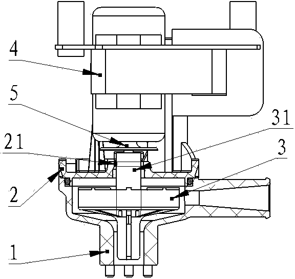
[0039] like figure 1 As shown, a drainage pump installed in an air conditioner includes a water pump casing (1), a motor casing (2), an impeller (3) and a motor (4) that drives the rotation of the impeller (3) to realize the drainage function , water retaining piece (5), the middle of the impeller (3) is provided with a wheel shaft (31) connected to the motor shaft (6) of the motor (4), and the upper part of the wheel shaft (31) runs through the motor casing (2 ) of the hollow portion (21). The upper part of the motor housing is provided with a water retaining piece (5), and the gap value A between the water retaining plate (5) and the end of the motor housing (2) ranges from 1 to 7mm (such as Figure 8 shown).

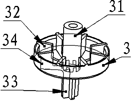
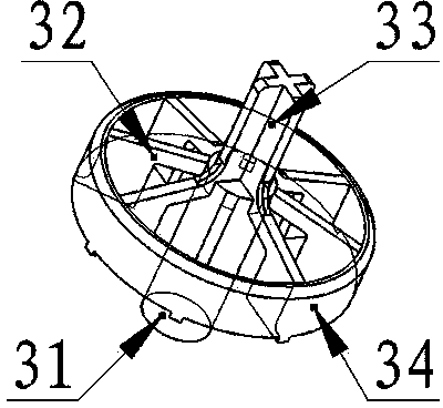
[0040] figure 2 and image 3 ...


PUM


Abstract

The invention discloses a draining pump which comprises a water pump shell (1), a motor shell (2), an impeller (3), a motor (4) and a water retaining piece (5), wherein the motor (4) drives the impeller (3) to rotate to realize a draining function. The draining pump is characterized in that the impeller (3) comprises a wheel shaft (31) in the middle, upper blades (32) and a flow limiting ring (34), the wheel shaft (31) is connected with a motor shaft (6) of the motor (4), the upper blades (32) are configured on the peripheral side of the wheel shaft (31) around the wheel shaft (31), the flow limiting ring (34) surrounds the upper blades (32), the upper blades (32) transits to a connection portion (321) through a rounded portion (322a) or a chamfered portion (322b) and are connected with the wheel shaft (31) through the connection portion (321), and lower ends of the upper blades (32) are provided with lower blades (33). By the arrangement, flow of the draining pump at the water level limit can be guaranteed, and noises during operation at the low water level can be restricted.

Description

technical field [0001] The invention relates to a drainage pump, in particular to a drainage pump installed in an air conditioner and used for discharging condensed water in a condensed water pan. Background technique [0002] When the indoor unit of the air conditioner is performing cooling operations, the moisture in the air will condense and adhere to the heat exchanger, and then slowly drip into the condensate pan under the heat exchanger. The condensed water in the water pan is discharged, so the drain pump for sucking and discharging condensed water is provided. This kind of drainage pump is connected with the impeller through the motor shaft of the driving motor. When the motor is driven to rotate the impeller, the water accumulated in the condensate pan will be sucked into the pump body from the water inlet of the pump casing. Under the action, it is discharged along the inner wall of the pump housing. This kind of drainage pump requires a certain head and flow rat...

Claims


Application Information

Patent Timeline
Patent Type & Authority Applications(China)
IPC IPC(8): F04D13/06F04D29/22
Inventor 刘超赵殿合邵韦石向新
Owner CHANGZHOU LEILI MOTOR SCI & TECH
Why Eureka
Try Eureka