Polarization-maintaining flat optical fiber coupling ball microscale sensor based on polarization state detection

A fiber coupling, polarization state technology, applied in instruments, measurement devices, optical devices, etc., can solve problems such as low primary amplification, inability to apply, and increased data volume, to meet industrial needs, improve adaptability, and processing speed. quick effect

Inactive Publication Date: 2014-07-02
HARBIN INST OF TECH
View PDF7 Cites 26 Cited by
  • Summary
  • Abstract
  • Description
  • Claims
  • Application Information

AI Technical Summary

Problems solved by technology

[0009] 1. It is difficult to further improve the touch displacement resolution of the detection system
The primary magnification of the existing detection system is low, resulting in a low overall magnification, and it is difficult to further improve the resolution of the touch displacement.
The fiber grating probe based on FBG Bending's micropore size measurement method cannot apply the main micro-touch displacement effect to the fiber grating, and the sensing signal converted into spectral information is weak, and the resolution of the system is very low
[0010] 2. The real-time performance of the detection system is poor, and it is difficult to achieve precise online measurement
The detection method adopted by the National Institute of Standards and Technology must use two-way area array CCDs to receive signal images, and a more complex image algorithm must be used to achieve high-resolution monitoring of the displacement of the optical fiber measuring rod, which results in a large amount of data that the measurement system needs to process The amount is greatly increased, which reduces the real-time performance of the detection system, and it is difficult to realize the synchronization of the aiming signal and the start and stop measurement in the process of small cavity size and two-dimensional coordinate measurement

Method used


Image

  • Polarization-maintaining flat optical fiber coupling ball microscale sensor based on polarization state detection
  • Polarization-maintaining flat optical fiber coupling ball microscale sensor based on polarization state detection

Examples


Embodiment Construction

[0022] Embodiments of the present invention will be described in detail below in conjunction with the accompanying drawings.

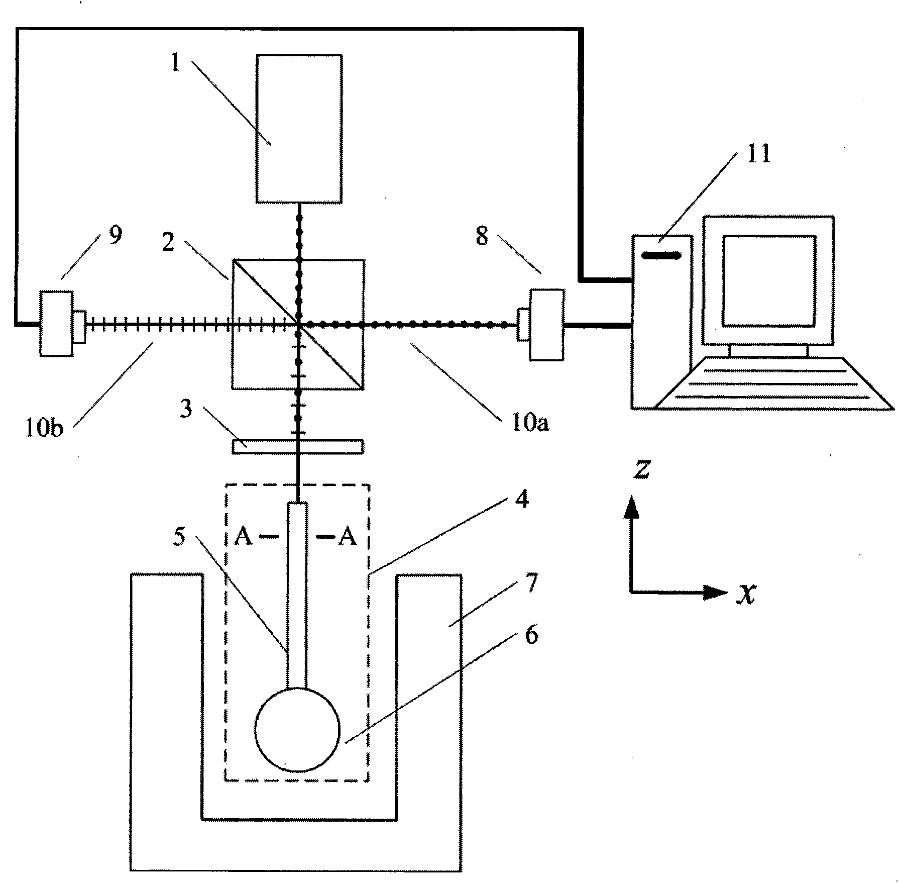
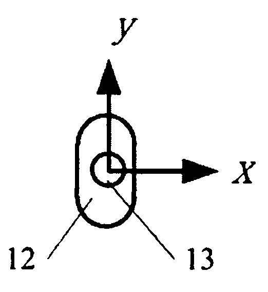
[0023] A polarization-maintaining flat fiber-coupled spherical microscale sensor based on polarization detection, the sensor includes a laser 1, a half-transparent and half-reflective prism 2, Wave plate 3, probe 4, polarization state detection device A8, polarization state detection device B9, computer 11, described probe 4 is made up of optical fiber 5 and coupling ball 6, and described optical fiber 5 is flat-clad polarization-maintaining optical fiber, Optical fiber 5 is made of flat cladding 12 and fiber core 13, and one end of optical fiber 5 is fixedly connected with coupling ball 6, and coupling ball 6 is used as the contact of probe 4; The wave plate 3 and the probe 4 are arranged in sequence, wherein the optical axis of the beam transmitted by the semi-transparent and half-reflective prism 2 of the outgoing light of the laser 1 coincides wi...


PUM


Abstract

The invention provides a polarization-maintaining flat optical fiber coupling ball microscale sensor based on polarization state detection and belongs to the technology of manufacturing and measurement of precise instruments. The polarization-maintaining flat optical fiber coupling ball microscale sensor comprises a laser, a semi-transparent semi-reflective prism, a quarter lambda wave plate, a probe, a polarization state detection device A, a polarization state detection device B and a computer, wherein the probe is composed of a flat package layer polarization-maintaining optical fiber and a coupling ball, and the laser, the semi-transparent semi-reflective prism, the quarter lambda wave plate and the probe are arranged in sequence. Emergent light of the laser is reflected and transmitted by the semi-transparent semi-reflective prism, and reflected light enters the polarization state detection device A; transmission light enters the probe, reverse transmission of a transmission light beam is achieved after the transmission light beam passes through the coupling ball, the transmission light exits from the probe, and emergent light passes through the quarter lambda wave plate, is reflected by the semi-transparent semi-reflective prism again and then enters the polarization state detection device B. When the difference value between the polarization state detected by the polarization state detection device B and the polarization state detected by the polarization state detection device A is changed, it can be determined that the probe is in contact with a detected hole. The polarization-maintaining flat optical fiber coupling ball microscale sensor is high in precision and high in speed.

Description

technical field [0001] The invention belongs to the manufacture and measurement technology of precision instruments, and mainly relates to a polarization-maintaining flat optical fiber coupling ball microscale sensor based on polarization state detection. Background technique [0002] With the continuous development of the aerospace industry, automobile industry, electronics industry and cutting-edge industries, the demand for precision and tiny components has increased dramatically. Due to the limitations of the space scale and the shadowing effect of the micro-components to be measured, as well as the influence of the measurement contact force, it is difficult to realize the precise measurement of the micro-component scale, especially the measurement of the depth of the micro-cavity components is difficult to increase, which has become a constraint to the development of the industry. "bottleneck". In order to achieve smaller size measurement and increase the measurement d...

Claims


Application Information

Patent Timeline
Patent Type & Authority Applications(China)
IPC IPC(8): G01B11/02
Inventor 崔继文冯昆鹏谭久彬
Owner HARBIN INST OF TECH
Why Eureka
Try Eureka