Slurry uniform filling system and slurry uniform filling method for testing flow sedimentation law of filling slurry

A technology for filling slurry and testing, which is applied in the direction of flow characteristics, preparation of test samples, and analysis of materials, etc. It can solve the problems of difficult control of the speed of slurry delivery, influence on the accuracy of test results, and instability of manual operation. Achieve the effect of saving manpower and material resources, avoiding instability, and simple structure

Active Publication Date: 2014-07-02
陕西嘉墨能源科技有限公司
View PDF6 Cites 4 Cited by
  • Summary
  • Abstract
  • Description
  • Claims
  • Application Information

AI Technical Summary

Problems solved by technology

On-site industrial experiments are time-consuming and costly, and it is difficult to carry out a large number of experiments; due to the lack of theory, the numerical simulation results are quite different from the actual results, and only qualitative analysis can be performed; and laboratory physical experiments can physically simulate on-site actual conditions. conditions, and the experimental cost is low, so it is the first choice for related research
[0003] When performing slurry filling in the laboratory filling slurry flow deposition law model test, ensuring that the slurry filling is uniform is the premise of accurate and reliable test results, but due to the difficulty in controlling the speed of slurry delivery and the instability of manual operation This makes it difficult to evenly fill the slurry in the model test, which affects the accuracy of the test results and cannot provide reliable test data for the study of the flow and deposition law of the filling slurry.

Method used


Image

  • Slurry uniform filling system and slurry uniform filling method for testing flow sedimentation law of filling slurry
  • Slurry uniform filling system and slurry uniform filling method for testing flow sedimentation law of filling slurry
  • Slurry uniform filling system and slurry uniform filling method for testing flow sedimentation law of filling slurry

Examples


Embodiment Construction

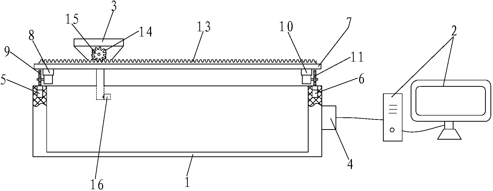
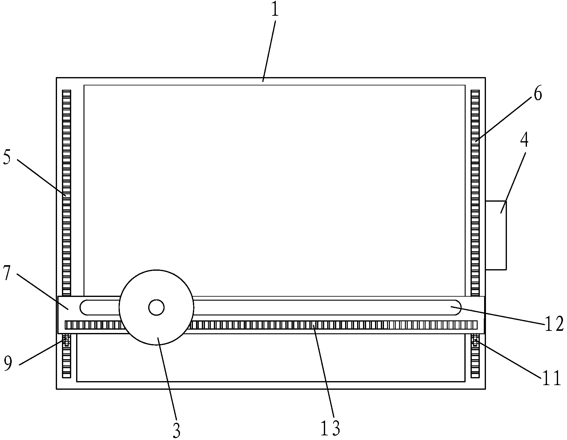
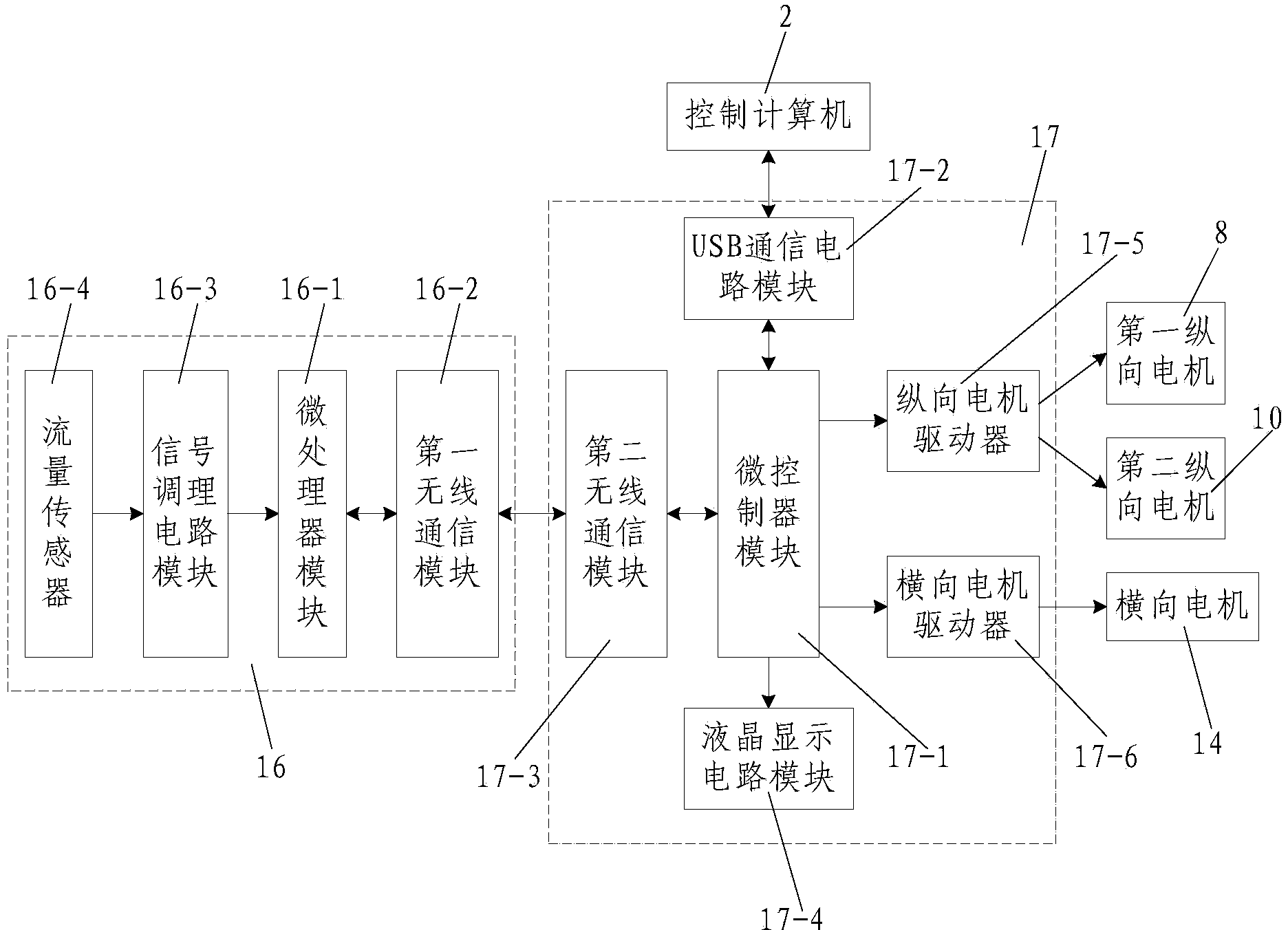
[0046] Such as figure 1 , figure 2 and image 3 As shown, the slurry uniform filling system for the flow deposition law test of the filling slurry of the present invention includes a cube-shaped test tank body 1 and a control computer 2, as well as a slurry funnel 3 arranged above the test tank body 1 and installed in the test tank body 1. The control box 4 on the outer wall of the tank body 1 is provided with a slurry uniform filling control system 17 inside; the top of the test tank body 1 in the width direction is respectively embedded with a first longitudinal rack 5 and a second longitudinal rack. The rack 6 is provided with a movable track beam 7 that can move along the first longitudinal rack 5 and the second longitudinal rack 6 along the length direction of the test cell 1, and the lower part of one end of the movable track beam 7 is equipped with a first A longitudinal motor 8, the output shaft of the first longitudinal motor 8 is fixedly connected with the first l...


PUM

PropertyMeasurementUnit
Lengthaaaaaaaaaa
Widthaaaaaaaaaa
Heightaaaaaaaaaa

Abstract

The invention discloses a slurry uniform filling system and a slurry uniform filling method for testing flow sedimentation law of filling slurry. The system comprises a test trough body, a control computer, a flow slurry funnel and a flurry uniform filling control system; the test trough body is provided with a first longitudinal rack and a second longitudinal rack, and a movable track beam is arranged along the length direction of the test trough body; the lower part of a lower filling pipe of the flow slurry funnel is provided with a wireless flow rate collector, and the wireless flow rate collector comprises a microprocessor module, a first wireless communication module, a signal conditioning circuit module and a flow rate sensor; the slurry uniform filling control system comprises a microcontroller module, a USB (universal serial bus) communication circuit module, a second wireless communication module, a liquid crystal display circuit module, a longitudinal motor drive device and a transverse motor drive device. The slurry uniform filling method comprises the following steps of I. formulating a blanking track of the flow slurry funnel; II. setting and transmitting blanking parameters; and III. Uniformly carrying out blanking on each blanking point through the flow slurry funnel. By adopting the slurry uniform filling system and the slurry uniform filling method, the test efficiency can be improved, and the filling uniformity of the slurry can be guaranteed.

Description

technical field [0001] The invention belongs to the technical field of research on the law of flow and deposition of filling slurry, and in particular relates to a uniform filling system and method for filling slurry for testing the law of flow and deposition of filling slurry. Background technique [0002] It is very meaningful to carry out the research on the flow deposition law of the filling slurry, but because the flow deposition of the complex multiphase flow of the filling slurry is very complicated, it is difficult to study, and the relevant research is relatively lacking. At present, there are mainly three research methods for the research of filling technology: field industrial test, laboratory physical experiment and numerical simulation. On-site industrial experiments are time-consuming and costly, and it is difficult to carry out a large number of experiments; due to the lack of theory, the numerical simulation results are quite different from the actual results...

Claims


Application Information

Patent Timeline
IPC IPC(8): G01N1/28G01N11/00
Inventor 刘浪
Owner 陕西嘉墨能源科技有限公司
Why Eureka
Try Eureka