Eureka AIR delivers breakthrough ideas for toughest innovation challenges, trusted by R&D personnel around the world.

Method and device achieving far-field super-resolution imaging

A super-resolution imaging and far-field technology, applied in the field of super-resolution imaging, can solve the problems of inability to achieve resolution, increase the difficulty of optical path adjustment, and inability to monitor two light spots in real time, achieving low adjustment difficulty, strong system flexibility, Strong anti-interference ability

Inactive Publication Date: 2014-07-02
INST OF OPTICS & ELECTRONICS - CHINESE ACAD OF SCI
View PDF6 Cites 10 Cited by
  • Summary
  • Abstract
  • Description
  • Claims
  • Application Information

AI Technical Summary

Problems solved by technology

However, it is not easy to achieve STED microscopic imaging. In STED microscopic imaging system, in order to obtain ultra-high resolution, a high numerical aperture objective lens with a numerical aperture of about 1.4 is generally used, so the excitation spot and the The STED spot size is below 500nm. At this time, the adjustment accuracy of the optical path system is very high to adjust the coincidence of the two spot positions. In addition, because the spot size is on the sub-wavelength level, ordinary imaging equipment such as CCD cannot reach it. With such a high resolution, it is impossible to monitor the positions of the two light spots in real time during the adjustment process, which increases the difficulty of optical path adjustment on the other hand

Method used


Image

  • Method and device achieving far-field super-resolution imaging
  • Method and device achieving far-field super-resolution imaging
  • Method and device achieving far-field super-resolution imaging

Examples


Embodiment Construction

[0024] The present invention will be described in detail below in conjunction with the accompanying drawings and embodiments, but the following embodiments are only limited to explaining the present invention, and the protection scope of the present invention is not limited thereto.

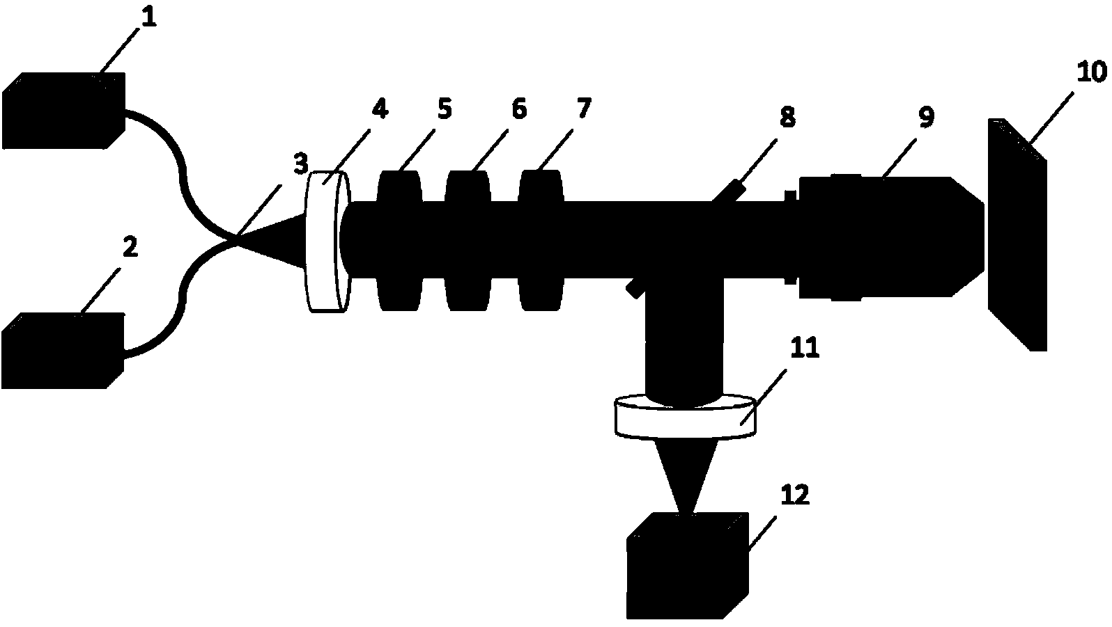
[0025] Such as figure 1 The shown method and device for realizing far-field super-resolution imaging include: 1. excitation light source; 2. STED light source; 3. single-mode fiber; 4. achromatic collimating lens; 5. polarizer; 6. double Wavelength wave plate; 7. Liquid crystal polarization converter; 8. Dichroic mirror; 9. High numerical aperture objective lens; 10. Three-dimensional nano-shift stage; 11. Focusing lens; 12. Light intensity detector.

[0026] The above-mentioned excitation light source and STED light source are respectively selected according to the fluorescent sample with a wavelength of λ 1 and lambda 2 laser, and according to λ 1 and lambda 2 Select the specific value of t...


PUM


Abstract

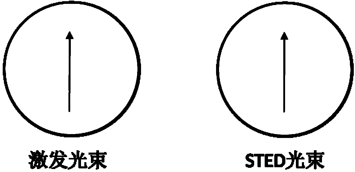
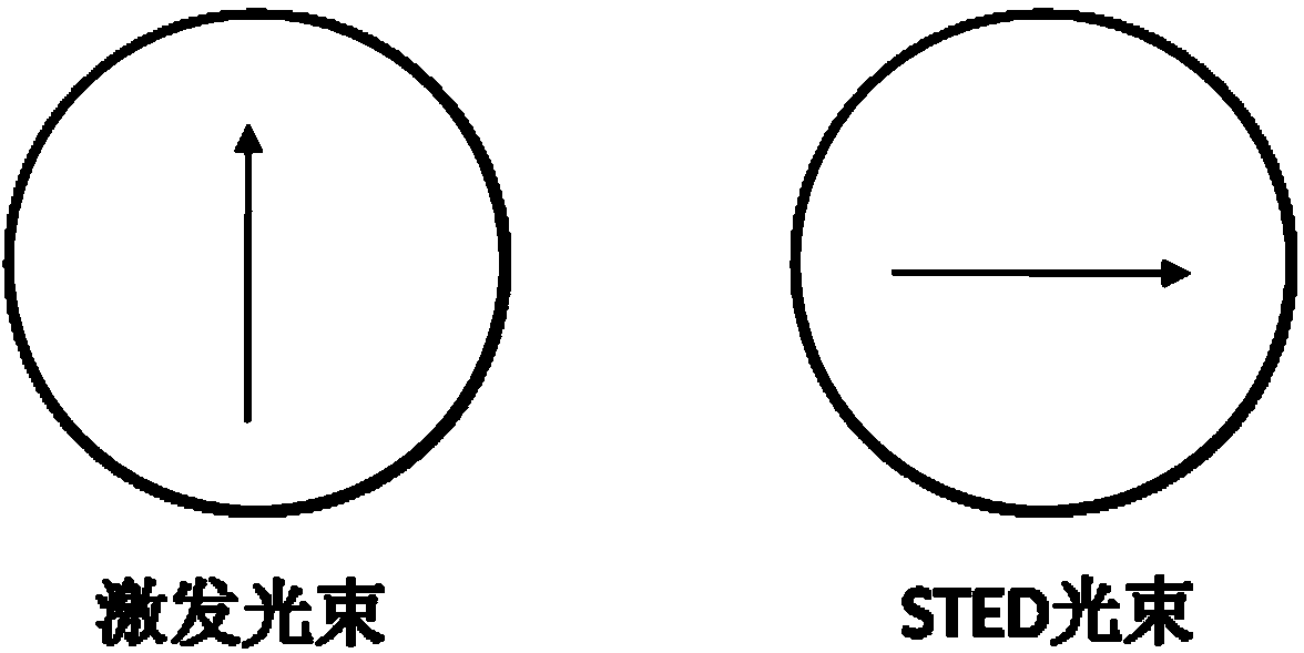
The invention provides a method and device achieving far-field super-resolution imaging. According to the method, exciting light and STED light are coupled simultaneously into single mode fiber so as to achieve the beam combining effect firstly, the exciting light and the STED light after beam combination pass through a polarizer and a dual-wavelength wave plate in sequence to be modulated to two perpendicular linear polarized light in the polarization direction, a liquid crystal polarization convertor is adopted, and the exciting light and the STED light are converted into the radial direction polarized light and the angle direction polarized light. The device achieving the method comprises an exciting light source, an STED light source, a collimating lens, the polarizer, the dual-wavelength wave plate, the liquid crystal polarization convertor, a dichroscope, a high numerical aperture lens, a three-dimensional nanometer displacement platform, a focusing lens and a light intensity detector. Through the coupling effect of the ingle mode fiber and the different focusing functions of the radial direction polarized light and the angle direction polarized light under the high numerical aperture, a circular excitation facular and an annular STED facular which are focused on the surface of a sample can be overlapped automatically, and difficulty of achieving the STED super-resolution imaging is reduced.

Description

technical field [0001] The invention belongs to the field of super-resolution imaging, and in particular relates to a method and a device for realizing far-field super-resolution imaging. Background technique [0002] Diffraction limit has always been an unavoidable problem in the field of super-resolution imaging. Due to the existence of diffraction limit, the resolution of traditional super-resolution microscopy imaging technology has been limited to above 200nm for a long time. With the continuous development of science and technology and the gradual deepening of understanding of the microscopic world, people are increasingly eager for super-resolution microscopic imaging technology with super-diffraction limit. In order to break through the limitation of the diffraction limit, researchers have carried out in-depth research along different approaches. With unremitting efforts, various super-resolution microscopic imaging techniques have been proposed one after another, an...

Claims


Application Information

Patent Timeline
IPC IPC(8): G02B27/58
Inventor 罗先刚王长涛赵泽宇王彦钦胡承刚蒲明薄王炯黄成刘玲罗云飞
Owner INST OF OPTICS & ELECTRONICS - CHINESE ACAD OF SCI
Why Eureka
Eureka Blog
Learn More