
Temperature difference power generation device and vehicle-mounted tail gas waste heat temperature difference power generation system

A technology of thermoelectric power generation and thermoelectric power generation module, which is applied in the directions of generators/motors, electrical components, and noise reduction devices, can solve the problems of low energy recovery rate and low power generation efficiency of thermoelectric power generation devices, etc., so as to improve energy utilization rate and improve Space utilization, strong practical effect

Inactive Publication Date: 2014-07-02
WUHAN UNIV OF TECH
View PDF5 Cites 13 Cited by
  • Summary
  • Abstract
  • Description
  • Claims
  • Application Information

AI Technical Summary

Problems solved by technology

[0004] The technical problem to be solved by the present invention is to provide a thermoelectric power generation device and a vehicle-mounted exhaust waste heat thermoelectric power generation system for the defects in the prior art that cannot effectively solve the problems of low energy recovery and utilization rate due to the low power generation efficiency of the thermoelectric power generation device

Method used


Image

  • Temperature difference power generation device and vehicle-mounted tail gas waste heat temperature difference power generation system
  • Temperature difference power generation device and vehicle-mounted tail gas waste heat temperature difference power generation system
  • Temperature difference power generation device and vehicle-mounted tail gas waste heat temperature difference power generation system

Examples


Embodiment Construction

[0033] In order to make the object, technical solution and advantages of the present invention clearer, the present invention will be further described in detail below in conjunction with the accompanying drawings and embodiments. It should be understood that the specific embodiments described here are only used to explain the present invention, not to limit the present invention.

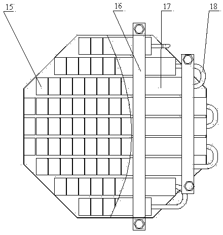
[0034] Such as Figure 1 ~ Figure 3 As shown, the thermoelectric power generation device includes an exhaust gas box 20 , a cooling water tank assembly, a thermoelectric power generation module assembly and a clamping plate 16 .

[0035] Such as Figure 4 As shown, the two ends of the exhaust box 20 are respectively provided with an intake manifold 8 and an exhaust manifold 11. The exhaust box 20 includes an air box body 26, a splitter fin 22, a guide fin 23 and a converging fin 24. The upper and lower surfaces of the box body 26 are regular octagons and are made of brass material. The diverter f...


PUM


Abstract

The invention discloses a temperature difference power generation device which comprises a tail gas tank, a cooling water tank assembly, a temperature difference power generation module assembly and a clamping plate. The two ends of the tail gas tank are provided with an intake manifold and an exhaust manifold respectively, and the tail gas tank comprises a gas tank body, a shunt fin, a flow guide fin and an afflux fin; the two ends of the cooling water tank assembly are provided with a water inlet manifold and a water outlet manifold respectively, the cooling water tank assembly comprises multiple cooling water tanks, and each cooling water tank comprises a water tank body and a flow guide plate; the hot end of the temperature difference power generation module assembly is attached to the two sides of the tail gas tank, the cold end of the temperature difference power generation module assembly is attached to one side of the cooling water tank assembly, and the temperature difference power generation module assembly comprises multiple temperature difference power generation modules; the clamping plate is arranged outside the cooling water tank assembly, and the two ends of the clamping plate are locked through bolts. The structure of the temperature difference power generation device is optimized and improved, power generation efficiency is improved, and the aim of improving the energy utilization rate is achieved.

Description

technical field [0001] The invention belongs to the technical field of automobile energy saving and emission reduction, and in particular relates to a thermoelectric power generation device and a vehicle exhaust waste heat thermoelectric power generation system. Background technique [0002] Resource scarcity and energy shortage are issues of common concern all over the world, and they are also technical bottlenecks restricting the rapid development of the traditional automobile industry powered by internal combustion engines. The utilization rate of limited vehicle fuel (gasoline and diesel) is also very low, and about two-thirds of the energy is dissipated into the air in the form of exhaust heat and mechanical loss. The purpose of the internal combustion engine does not match, and it is urgent to improve and improve the traditional internal combustion engine working process and emission process, and invent new energy-saving and emission-reducing mechanisms. [0003] Trad...

Claims


Application Information

Patent Timeline
IPC IPC(8): H02N11/00F01N5/02
CPCY02T10/16Y02T10/12
Inventor 邓亚东王新予楚拯中苏楚奇李浩王文帅王顺民辛宇华
Owner WUHAN UNIV OF TECH
Learn More