
Standing wave electron linear accelerator device and method thereof

A linear accelerator and electron technology, applied in linear accelerators, irradiation devices, electrical components, etc., can solve the problems of low acceleration efficiency, increased energy dissipation, and inability to provide, and achieve the effect of vertical compactness and stable working state.

Active Publication Date: 2014-07-02
TSINGHUA UNIV +1
View PDF14 Cites 4 Cited by
  • Summary
  • Abstract
  • Description
  • Claims
  • Application Information

AI Technical Summary

Problems solved by technology

The main disadvantage of this method is that the change of the gradient in the low-energy section of the accelerating tube will lead to an increase in energy dissipation and deteriorate the beam quality; in order to solve the problem of large energy dissipation, U.S. Patents US2920228 and US3070726 disclose an accelerator, which uses Two-stage traveling wave tubes accelerate electrons, the first stage accelerates electrons to close to the speed of light, and the second stage realizes energy modulation by changing the microwave phase
The main disadvantage of this method is that the traveling wave acceleration structure is adopted, and the acceleration efficiency is low; in order to solve the problem of low efficiency, US Patent No. 4,118,653 proposes an acceleration structure combining traveling waves and standing waves
The main disadvantage of this method is that two types of accelerating structures are required, resulting in scattered structures and complex peripheral circuits; in order to obtain a compact accelerating structure, US Patent No. 4,024,426 proposes a space-edge coupled standing wave accelerator, which is achieved by changing the microwave phase difference between the accelerating tubes. Realize energy modulation
The main disadvantage of this method is that the structure of the accelerating tube is complex and the process is too difficult, making the solution difficult to realize; in order to obtain a simple accelerating structure and high accelerating efficiency, US Patents US4286192 and US4382208 respectively disclose a kind of accelerator, which is coupled with a linear accelerator on the side. Several (one or two) perturbation rods that can adjust the phase by adjusting the insertion depth are added to the cavity
The main disadvantage of this method is that the energy adjustment range is small, and the adjustment of the perturbation rod requires professional skills. The main disadvantage of this method is that the accelerator has a large lateral dimension, the microwave feeding system is complicated, and it cannot provide low-energy (~1MeV) electron beams.
[0005] To sum up, the current X-ray tubes and linear accelerators either cannot cover the energy range of 0.5MeV to 2MeV, or the structure is complex and difficult to realize. Therefore, it is required to have an output electron energy covering this range. The structure is simple, easy to implement and the cost is acceptable. Accelerator

Method used


Image

  • Standing wave electron linear accelerator device and method thereof
  • Standing wave electron linear accelerator device and method thereof
  • Standing wave electron linear accelerator device and method thereof

Examples


Embodiment Construction

[0034]Specific embodiments of the present invention will be described in detail below, and it should be noted that the embodiments described here are only for illustration, not for limiting the present invention. In the following description, numerous specific details are set forth in order to provide a thorough understanding of the present invention. It will be apparent, however, to one of ordinary skill in the art that these specific details need not be employed to practice the present invention. In other instances, well-known circuits, materials or methods have not been described in detail in order to avoid obscuring the present invention.

[0035] Throughout this specification, reference to "one embodiment," "an embodiment," "an example," or "example" means that a particular feature, structure, or characteristic described in connection with the embodiment or example is included in the present invention. In at least one embodiment. Thus, appearances of the phrases "in one...


PUM


Abstract

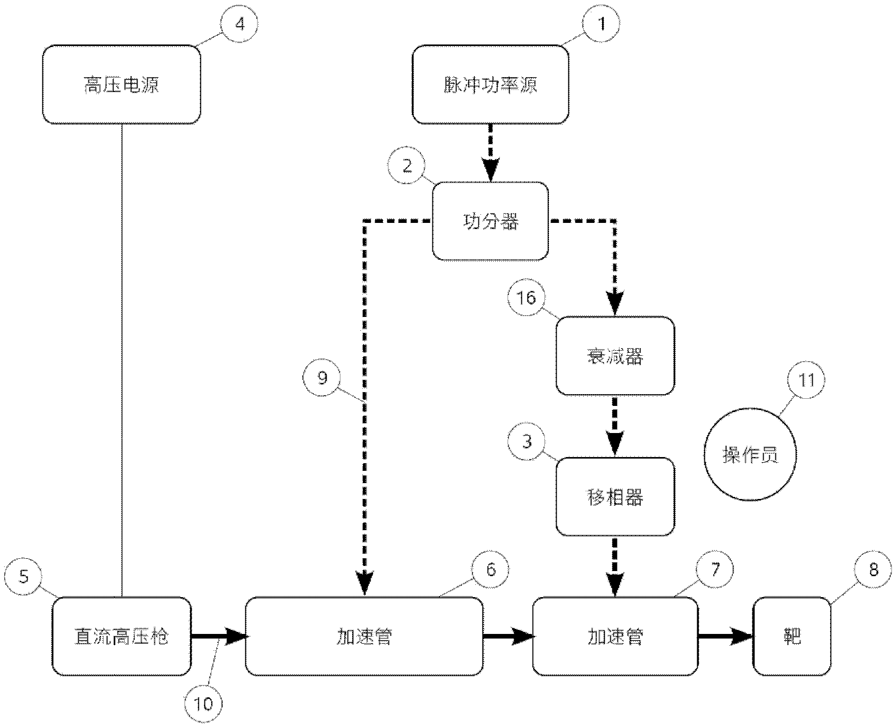
A standing wave electron linear accelerating apparatus and a method thereof are disclosed. The apparatus comprises an electron gun configured to generate electron beams; a pulse power source configured to provide a primary pulse power signal; a power divider coupled downstream from the pulse power source and configured to divide the primary pulse power signal outputted from the pulse power source into a first pulse power signal and a second pulse power signal; a first accelerating tube configured to accelerating the electron beams with the first pulse power signal; a second accelerating tube configured to accelerate the electron beams with the second pulse power signal; a phase shifter configured to continuously adjust a phase difference between the first pulse power signal and the second pulse power signal so as to generate accelerated electron beams with continuously adjustable energy at output of the second accelerating tube.

Description

technical field [0001] Embodiments of the present invention relate to the technical field of standing wave electron linear accelerators, especially the fields of medical imaging and irradiation using accelerators as radiation sources. Background technique [0002] Modern medicine increasingly uses X-rays for diagnosis and treatment. In existing medical imaging systems, X-ray tubes are mainly used to generate X-rays with energy lower than 500keV (the energy here refers to the energy of the electron beam before hitting the target), and X-rays with energy higher than 2MeV are mainly generated by low-energy electron linear accelerators. , X-ray sources with energy between 0.5MeV and 2MeV are still almost blank (of course there are 600kV X-ray tubes, but they are very expensive). Because in this energy interval, the ability of X-ray tube has almost reached the limit, its production cost climbs rapidly along with the raising of energy; And the cost of electron linear accelerator ...

Claims


Application Information

Patent Timeline
IPC IPC(8): H05H9/04
CPCH05G1/32H05H9/04H05H9/048H05H7/12H05H7/22G21K5/02H05H9/00H05G2/00
Inventor 唐传祥张哲靳清秀施嘉儒陈怀璧黄文会郑曙昕刘耀红
Owner TSINGHUA UNIV
Learn More