Nitrogen-increasing method for molten steel of ultra-low carbon enamel steel

An enamelled steel, ultra-low carbon technology, applied in the field of iron and steel metallurgy, can solve the unsolved problems such as the matching of nitrogen increasing operation time, refining cycle and continuous casting rhythm.

Active Publication Date: 2015-08-26
SHOUGANG CORPORATION
View PDF5 Cites 0 Cited by
  • Summary
  • Abstract
  • Description
  • Claims
  • Application Information

AI Technical Summary

Problems solved by technology

The present invention reduces the production cost by partially replacing vanadium-nitrogen alloy and substituting nitrogen for argon in the refining stage, but still does not solve the problem of matching the nitrogen increasing operation time, refining cycle and continuous casting rhythm

Method used


Image

  • Nitrogen-increasing method for molten steel of ultra-low carbon enamel steel
  • Nitrogen-increasing method for molten steel of ultra-low carbon enamel steel
  • Nitrogen-increasing method for molten steel of ultra-low carbon enamel steel

Examples


Embodiment approach 1

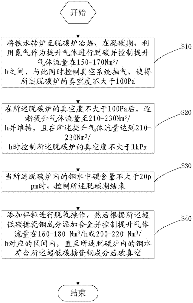
[0020] Such as figure 1 as shown, figure 1 It is a schematic flowchart of a method for increasing nitrogen in molten steel of ultra-low carbon enamel steel provided in Embodiment 1 of the present invention.

[0021] A method for increasing nitrogen in ultra-low carbon enamel molten steel provided by the invention, comprising

[0022] Step S10: transfer the molten iron to the decarburization furnace for smelting. During the decarburization period, use nitrogen as the lifting gas for decarburization and control the flow rate of the lifting gas at 150-170Nm 3 / h, at the same time control the vacuum system pumping, so that the vacuum degree of the decarburization furnace is not greater than 100Pa. In this embodiment, after the molten iron is transferred to the decarburization furnace, the decarburization furnace is firstly subjected to the operation of temperature measurement and oxygen determination, and the natural decarburization process or forced oxygen blowing is determined...

Embodiment approach 2

[0033] The technical solution of the present invention will be further described below through 6 smelting examples of ultra-low carbon enamel steel molten steel smelting.

[0034] The control of the vacuum system during decarburization is: use the 2-stage pump of the vacuum pump to pump air, so that the vacuum degree of the decarburization furnace is below 100Pa, and the decarburization is performed for 5-8 minutes. At this time, the vacuum degree of the decarburization furnace is not greater than 1kPa. At the same time, input lifting gas nitrogen to the decarburization furnace, and the lifting gas flow rate is 150-170Nm 3 / h. During the 5-8 minutes of decarburization, gradually increase the gas flow rate to 210-230Nm 3 / h between. The whole decarburization time is about 15-18min, maintain this boost gas flow rate 210-230Nm 3 / h level to the end of decarburization, at this time the carbon content in the molten steel in the decarburization furnace is not more than 20ppm.

...


PUM


Abstract

The invention belongs to the technical field of ferrous metallurgy, and particularly relates to a method for adding nitrogen to ultra-low carbon enamel molten steel. The method comprises the following steps: decarbonizing by utilizing nitrogen as a lift gas while controlling the flow of the lift gas at 150-170Nm<3> / h, and exhausting, so that the vacuum degree of a decarburization furnace is not greater than 100Pa; gradually lifting the flow of the lift gas to 210-230Nm<3> / h, and finishing the decarburization stage until the carbon content in the molten steel is not greater than 20ppm, wherein the vacuum degree of the decarburization furnace is not greater than 1kPa; carrying out a deoxidation operation; adding alloy and controlling the flow of the lift gas in an interval corresponding to 160-180Nm<3> / h or 200-220Nm<3> / h; breaking vacuum until the molten steel accords with the ultra-low carbon enamel molten steel ingredient. Nitrogen is added in decarburization by controlling the flow of the lift gas of nitrogen, the vacuum degree and the decarburization time of the decarburization furnace in the decarburization and deoxidation processes, so that the nitrogen content of a finished product can be accurately controlled, use of alloy is reduced, and the cost is reduced.

Description

technical field [0001] The invention belongs to the technical field of iron and steel metallurgy, in particular to a method for increasing nitrogen in molten steel of ultra-low carbon enamel steel. Background technique [0002] Nitrogen is easy to combine with Al, Ti, Nb, B and other elements to form compounds. When nitrogen combines with B elements to form boron nitride, it will not be able to play the role of nitrogen and increase the source of cracks during deformation. Therefore, for most steel types, nitrogen is a harmful element, and its content should be reduced as much as possible during the smelting process. However, for ultra-low carbon enamelled steel, not only deep drawing performance is required, but also in order to ensure sufficient second-phase particles to meet the anti-knock performance requirements of the steel, nitrogen needs to combine with titanium in the steel to form nitrides, and then Nitrogen needs to be added to the molten steel during the smeltin...

Claims


Application Information

Patent Timeline
Patent Type & Authority Patents(China)
IPC IPC(8): C21C7/10C21C7/06C21C7/068
Inventor 李一丁季晨曦崔阳王志鹏田志红赵长亮黄财德刘再旺曾智
Owner SHOUGANG CORPORATION
Why Eureka
Try Eureka