
Low pressure filtration heat exchanger

A heat exchanger and low-pressure technology, which is applied in the field of low-pressure filter heat exchangers, can solve the problems of increasing the difficulty of opening nozzles, and achieve the effects of increased working life, long contact time, and smooth flow

Inactive Publication Date: 2014-07-09
上海依相动力系统有限公司
View PDF10 Cites 0 Cited by
  • Summary
  • Abstract
  • Description
  • Claims
  • Application Information

AI Technical Summary

Problems solved by technology

[0002] Due to global warming, PM2.5 and smog have increased significantly, resulting in a large increase in the number of natural gas engines and car ownership. On gas engines, due to the needs of emissions and economy, a large number of natural gas injection control systems are used. The nozzle in the injection system is the most important. It is an important and most precise gas metering component. However, due to the fact that natural gas will be continuously mixed with some oil and water during the process of refining and filling at gas stations, the temperature of natural gas after the pressure reducer will be low when the engine is running at high speed and heavy load. Below zero degrees Celsius, the viscosity of the oil in the natural gas increases, and the water condenses and freezes. The oil and water flow into the nozzle with the natural gas, and continuously gather around the static iron core and the moving iron core inside the nozzle, which increases the difficulty of opening the nozzle.

Method used


Image

  • Low pressure filtration heat exchanger
  • Low pressure filtration heat exchanger
  • Low pressure filtration heat exchanger

Examples


Embodiment Construction

[0039] In order to make it easy to understand the technical means, creative features, objectives and effects achieved by the present invention, the present invention will be further explained below in conjunction with specific drawings.

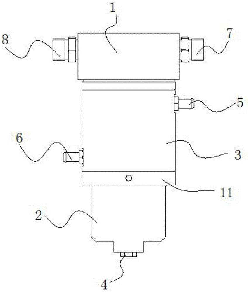
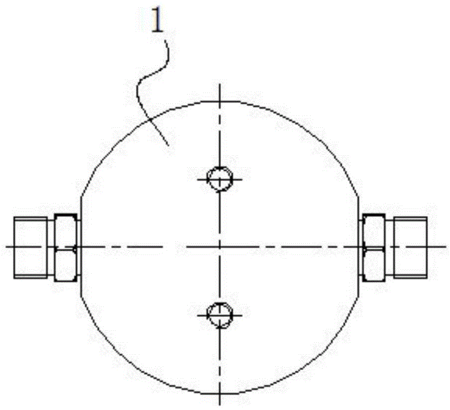
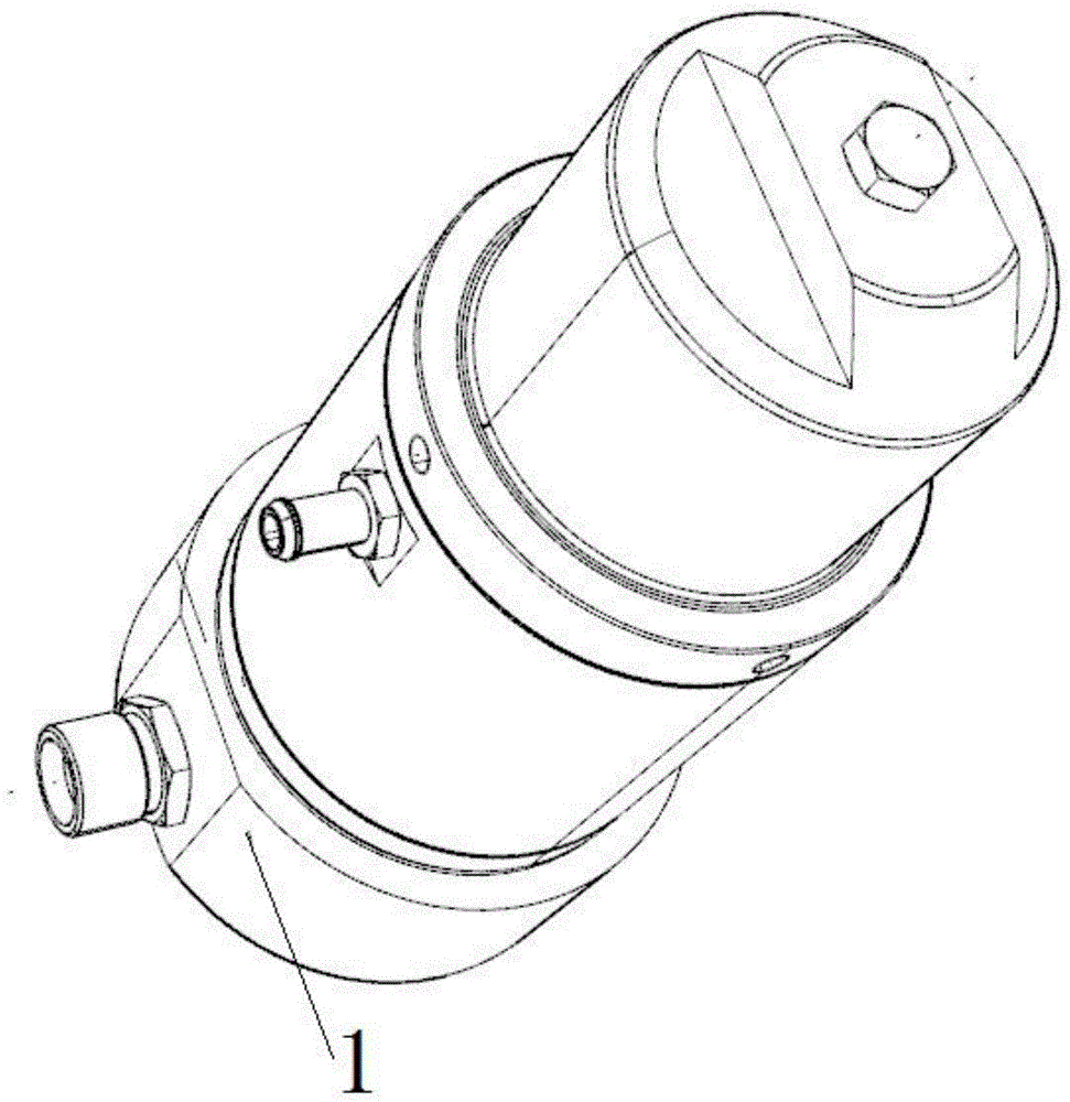
[0040] figure 1 It is a front view of the low-pressure filter heat exchanger of the present invention, wherein the symbol 1 is the upper shell unit of the low-pressure filter heat exchanger, which is generally a cylindrical structure, and the upper shell unit of the cylindrical structure has a cavity inside Body, and the lower part is open, which is convenient for docking the lower housing unit. The upper housing unit 1 consists of an annular housing wall 1a and an upper cover portion 1b forming a bottomed cylindrical shape with an open end (see Figure 4~8 ), the inner wall of the upper housing unit is provided with an internal thread structure for assembly near the opening. The gas inlet end 7 and the gas outlet end 8 arranged coaxially are in...


PUM


Abstract

The invention discloses a low pressure filtration heat exchanger. The low pressure filtration heat exchanger is provided with an upper housing unit and a lower housing unit which are assembled into a whole in detachable mode and distributed from the top down, and the interior of the low pressure filtration heat exchanger is provided with a fuel gas flow cavity, wherein the fuel gas flow cavity is provided with a fuel gas inlet end and a fuel gas outlet end which are connected with an automobile fuel gas feed pipeline, a fuel gas flow guidance structure used to guide fuel gas which enters into the upper housing unit from the fuel gas inlet end into the fuel gas flow cavity so as to enable the flue gas to fully touch the housing wall of the lower housing unit is arranged in the upper housing unit, a discharge device used to discharge sewage is arranged at the bottom of the lower housing unit, a housing structure is arranged on the external circumference of the lower housing unit, the housing structure and the lower housing unit together form a closed engine coolant flow cavity structure, and the engine coolant flow cavity structure is provided with a cooling medium inlet and a cooling medium outlet which are arranged in stagger mode from the top down. The low pressure filtration heat exchanger can guarantee opening reliability of a nozzle of a natural gas engine when the natural gas engine runs in low temperature severe environments, at high speed and under heavy load, and is low in cost.

Description

Technical field [0001] The invention relates to a heat exchange device for a gas vehicle, in particular to a low-pressure filter heat exchanger. Background technique [0002] Due to global warming, a large increase in PM2.5 and smog has led to a large increase in the number of natural gas engines and automobiles. For gas engines, due to the needs of emissions and economy, a large number of natural gas injection control systems are used. In the injection system, nozzles are the most important. An important and most precise gas metering component, but because natural gas is constantly mixed with some oil and water during the process of refining and filling stations, the temperature of natural gas after the pressure reducer is low when the engine is running at high speed and high load Below zero degrees Celsius, the viscosity of the oil in the natural gas increases, the water condenses and freezes, and the oil and water flow into the nozzle with the natural gas, and continue to gath...

Claims


Application Information

Patent Timeline
Patent Type & Authority Applications(China)
IPC IPC(8): F02M21/06
CPCY02T10/30
Inventor 徐贤伟李键段洪强吴新星刘军李源龙郑涛孙懿李贵宾孙孝亮
Owner 上海依相动力系统有限公司
Learn More