Track traffic rotation speed sensor based on magnetism principle

A speed sensor, rail transit technology, applied in linear/angular velocity measurement, instrument, speed/acceleration/shock measurement, etc., can solve the problem of inability to read the speed signal of the magnetoelectric speed sensor, increase safety hazards, increase operating costs, etc. To achieve the effect of reliable and flexible connection, improved anti-interference, high production and assembly efficiency

Inactive Publication Date: 2014-07-09
NINGBO CRRC TIMES TRANSDUCER TECH CO LTD
View PDF5 Cites 13 Cited by
  • Summary
  • Abstract
  • Description
  • Claims
  • Application Information

AI Technical Summary

Problems solved by technology

[0003] Now rail transit is developing rapidly, and the speed of locomotives is getting higher and higher. The safety of locomotives running at high speed cannot be ignored, so the monitoring of the rotational speed of locomotive shafts is essential. At present, the sensors used to measure the speed of locomotive shafts are mainly photoelectric speed sensors, but The defects of the photoelectric speed sensor applied to the locomotive are as follows: 1. The light source of the photoelectric module is a light-emitting diode, and the light-emitting diode is always aging. After a period of use, its light intensity will decrease significantly, and a special regulator is used to compensate for the loss. Gradually increase the current through the light-emitting diode, but this will further accelerate its aging process. For safety reasons, the photoelectric module must be replaced after 300,000 kilometers or five years of use, which increases operating costs. In addition, the photosensitive elements in the photoelectric module are also It will gradually age, the performance will deteriorate, and the safety hazard will be increased.
2. When used to measure the speed of the rotating shaft, the rotating shaft, transmission shaft, connector, etc. will use lubricating oil for lubrication or sealing, while the grating and photoelectric module of the photoelectric speed sensor are easily polluted by oil, water vapor, dust, foreign matter, etc., resulting in The optical slit is blocked, resulting in product failure
[0004] There are also defects in the use of Hall sensors or other magnetoelectric sensors in rail transit. 1. The high speed of high-speed rail vehicles and the precise positioning of the stop position require strict monitoring of the speed of the locomotive. The current Hall sensor accuracy cannot reach the track traffic locomotive requirements
2. Under the condition of low speed, other magnetoelectric speed sensors have no signal output, which makes the locomotive control system unable to read the speed signal of the magnetoelectric speed sensor when the locomotive is at low speed

Method used


Image

  • Track traffic rotation speed sensor based on magnetism principle
  • Track traffic rotation speed sensor based on magnetism principle
  • Track traffic rotation speed sensor based on magnetism principle

Examples


Embodiment 1

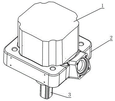
[0033] Such as figure 1 The magnetic principle-based speed sensor used for rail transit is shown, the cover body 1 is fixed above the sensor seat 2, the shaft assembly 3 is fixed below the seat 2, and the space enclosed by the seat 2 and the cover body 1 Set up the speed measuring part of the sensor.

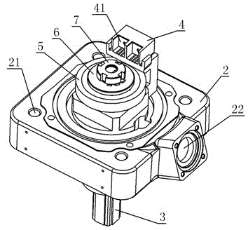
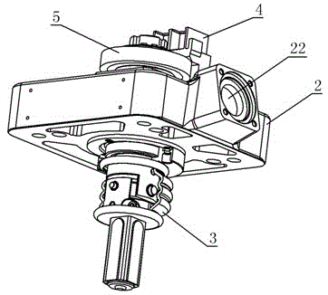
[0034] The structure after removing the cover is as follows figure 2 , image 3 , Figure 4 and Figure 5 As shown, a plurality of fixing holes 21 are set on the device base 2, and the fixing holes 21 are used to fix the device base 2 on the parts outside the rotating shaft of the rail transit locomotive. The side wall of the device base 2 is provided with a wiring channel 22, and the wiring channel 22 The inner space of the connector seat 2 and the cover body 1 is used for laying power lines, signal lines, etc. inside the channel, and the outer interface of the wiring channel 22 can fix the cable connector of the sensor and the like. A circular hole is provided at the cen...

Embodiment 2

[0046] The structure and connection relationship of the cover body, device seat, shafting assembly, magnetic code disc, pressure plate, nut and stop washer of the sensor in this embodiment are the same as in the first embodiment, and the structure of the circuit module 4 is the same as that in the first embodiment The same, the difference is that two circuit modules 4 are fixed on the device base 2, such as Figure 10 shown. The magnetic sensitive elements 42 of the two circuit modules 4 are located on the side of the magnetic code disk 5 . Setting two circuit modules 4 can achieve the purpose of redundant design, and the speed signals detected by the two circuit modules 4 can be sent to the rail transit monitoring system, braking system, etc. to realize multi-channel speed signal output.

Embodiment 3

[0048] The structure and connection relationship of the cover body, device seat, shafting assembly, magnetic code disc, pressure plate, nut and stop washer of the sensor in this embodiment are the same as in the first embodiment, and the structure of the circuit module 4 is the same as that in the first embodiment The same, the difference is that three circuit modules 4 are fixed on the device base 2, such as Figure 11 shown. The magnetic sensitive elements 42 of the three circuit modules 4 are all located on the side of the magnetic code disk 5 . The three circuit modules 4 can also realize redundant design and multiple outputs.


PUM


Abstract

The invention discloses a track traffic rotation speed sensor based on the magnetism principle. The track traffic rotation speed sensor based on the magnetism principle comprises a base, a shaft system assembly and a cover. Circuit modules and a magnetic code disc are arranged in a cavity defined by the base and the cover. The magnetic code disc is fixed to the upper end of a rotary shaft. A plurality of magnetic pole pairs are arranged on the circumference of the magnetic code disc. The N poles and the S poles of the magnetic pole pairs are distributed alternately. Each circuit module comprises a magnetic sensitive element and a circuit board. The magnetic sensitive elements are right opposite to the magnetic poles of the magnetic pole pairs of the magnetic code disc. As the magnetic code disc rotates, the N poles and the S poles of the magnetic pole pairs approach the magnetic sensitive elements alternately, the magnetic sensitive elements sense the magnetic field changes, and signal processing circuits in the circuit boards process sensing signals and output pulse signals. The multiple circuit modules can be fixed in the cavity, each circuit module is internally provided with two magnetic sensitive elements with the phase difference of 90 degrees. The track traffic rotation speed sensor based on the magnetism principle can measure the rotation speed of the rotary shaft accurately, and is good in pollution resistance, not prone to aging and simple in structure.

Description

technical field [0001] The invention relates to a rotational speed sensor, in particular to a sensor for detecting the rotational speed of a rail transit locomotive shaft. Background technique [0002] At present, there are mainly the following types of speed sensors. One is the photoelectric speed sensor. The photoelectric speed sensor is composed of a photoelectric module, a grating, a casing, a transmission pump, a connector and a cable. The principle is that the output frequency is proportional to the electrical pulse signal of the wheel shaft speed; the other is the Hall speed sensor. The Hall speed sensor is installed on the end cover of the locomotive gear. The sensor is composed of a mounting flange, a Hall element, a magnetic steel, a casing and Composed of output cables, the Hall element is placed in a fixed magnetic field. As the gear rotates, the gear teeth and tooth slots alternately approach the Hall element. The Hall element senses the change in the surroundin...

Claims


Application Information

Patent Timeline
Patent Type & Authority Applications(China)
IPC IPC(8): G01P3/487
Inventor 马锡敏姚利民叶明盛周冲陈增贤
Owner NINGBO CRRC TIMES TRANSDUCER TECH CO LTD
Why Eureka
Try Eureka