Optical isolation method and device

An optical isolation and optical wedge technology, applied in the field of optical isolation, can solve the problems of limited power tolerance of optical isolation devices, high material cost, large device package size, etc., achieve optimal reflected light blocking performance, achieve separation, and reduce packaging. The effect of size

Inactive Publication Date: 2017-04-12
浙江奥智光电科技有限公司
View PDF9 Cites 0 Cited by
  • Summary
  • Abstract
  • Description
  • Claims
  • Application Information

AI Technical Summary

Problems solved by technology

In the case of ensuring the optical rotation angle, the outer dimension of the magnetic ring that provides the magnetic field for the Faraday medium increases rapidly with the increase of its inner diameter (that is, the Faraday aperture). Therefore, this design not only has a high material cost for the Faraday medium, but also The package size of the device is large and the power handling of the optical isolation device is limited

Method used


Image

  • Optical isolation method and device
  • Optical isolation method and device
  • Optical isolation method and device

Examples


Embodiment 1

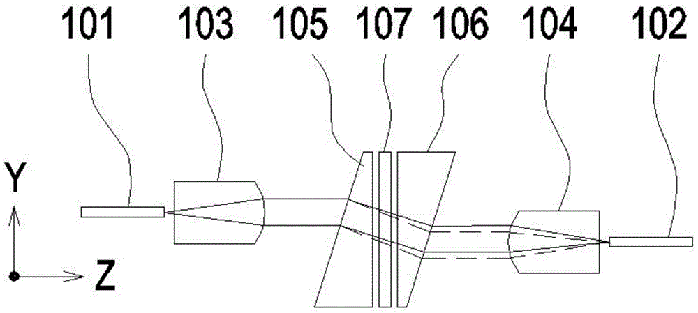
[0034] The invention discloses an optical isolation method, which separates the forward light into two polarized light components, so that a distance is generated in space and an included angle is formed in the propagation direction; After the irreversible light polarization state is rotated, the two polarized light components are combined and output according to the opposite process of separation; the reversed light is separated into two polarized light components, so that a distance is generated in space and the propagation direction forms an included angle; reversed The two polarized light components of the light will deviate from the forward light path after the irreversible light polarization state rotation at the spatial intersection point; set a reverse diaphragm at the place where the forward and reverse light paths do not overlap, pass the forward light and block the reverse direction Light, to achieve the purpose of optical isolation.

[0035] Polarization splitter ...

Embodiment 2

[0051] The difference between the optical isolation device disclosed in this embodiment and the optical isolation device disclosed in Embodiment 1 is that the structure of the polarization beam splitting device is different. The polarization beam splitting device disclosed in this embodiment will be described in detail below, and the optical isolation device The same parts as those in Example 1 will not be described in detail.

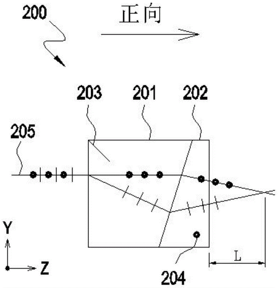
[0052] Polarization splitting device 300 such as Figure 3A and Figure 3BAs shown, it consists of a birefringent parallel displacement crystal 301 and a non-birefringent roof prism 302. The optical axis 303 of the parallel displacement crystal 301 forms an included angle of 45 degrees with the Y axis, and its thickness depends on the position L of the crossing point of the required beams. choose. When a beam of incident light 304 with a random polarization state is perpendicularly incident on the parallel displacement crystal 301 along the positive ...

Embodiment 3

[0055] The difference between the optical isolation device disclosed in this embodiment and the optical isolation device disclosed in Embodiment 1 is that the structure of the polarization beam splitting device is different. The polarization beam splitting device disclosed in this embodiment will be described in detail below, and the optical isolation device The same parts as those in Example 1 will not be described in detail.

[0056] Polarization splitting device 400 such as Figure 4A and Figure 4B As shown, it consists of a birefringent parallel displacement crystal 401 and a non-birefringent optical wedge 402. The optical axis 403 of the parallel displacement crystal 401 forms an included angle of 45 degrees with the Y axis, and its thickness depends on the position L of the crossing point of the required beams. choose. When a beam of incident light 404 with a random polarization state is vertically incident on the parallel displacement crystal 401 along the positive d...


PUM


Abstract

The invention discloses an optical isolation method. Forward light is split into two polarized light components in a polarization light-splitting device at the incident end, light paths of the two polarized light components are intersected after the two polarized light components are emergent from the polarization light-splitting device at the incident end, a polarization rotator is arranged at the intersection, the two polarized light components are intersected in internal space of the polarization rotator, backward light after passing the polarization rotator deflects angularly and deflect parallelly in the polarization light-splitting device at the incident end, and the backward light is separated from the forward light paths. The invention further discloses an optical isolation device which comprises an input optical fiber, an output optical fiber, two collimating lenses, two polarization light-splitting devices and one polarization rotator. Power bearing capacity can be improved, requirements on clear aperture of the Faraday rotator are lowered, and package size of the device is reduced.

Description

technical field [0001] The invention relates to optical isolation technology of fiber lasers, in particular to a polarization-independent high-power optical isolation method and device applied to fiber lasers. Background technique [0002] Because of its good beam quality, high conversion efficiency and good stability, fiber laser has become the representative of the third-generation laser technology, and has unparalleled technical advantages compared to other lasers. At present, high-power fiber lasers have been widely used in many fields such as industrial processing, optical fiber communication, printing roll making, military defense, and medical equipment. In the long run, fiber lasers will gradually replace high-power carbon dioxide lasers and YAG high-power lasers in most applications. [0003] When the fiber laser is working, in addition to the forward-transmitting working light in its optical path, there are also reverse-transmitting reflected light due to various r...

Claims


Application Information

Patent Timeline
Patent Type & Authority Patents(China)
IPC IPC(8): G02F1/09
Inventor 林先锋季国伟赖正伟
Owner 浙江奥智光电科技有限公司
Why Eureka
Try Eureka