Coaxial resonant cavity microwave light source

A coaxial resonant cavity and microwave technology, applied in the field of plasma light sources, can solve the problems of dielectric loss, affecting light efficiency, and high price, and achieve high quality factor Q value, high light transmittance, and increased light transmission surface. Effect

Inactive Publication Date: 2014-07-09
李碧霞
View PDF4 Cites 6 Cited by
  • Summary
  • Abstract
  • Description
  • Claims
  • Application Information

AI Technical Summary

Problems solved by technology

At the beginning of the 20th century, dozens of enterprises in my country successively launched high-power microwave sulfur lamps above 1000W, but now, the production and use of high-power microwave sulfur lamps have dropped significantly.
But this kind of microwave light source also has disadvantages: 1. Semiconductor microwave source technology is currently expensive, so the price of the whole machine is also high. Generally, a 300W LEP lamp is priced at about 6,000 yuan; 2. Due to the use of dielectric ceramics As a microwave resonant cavity, it will bring dielectric loss and affect the improvement of light efficiency; 3. The bulb contains mercury and 85 Kr is radioactive, not really an environmentally friendly product
However, the price of LEP products is still too expensive at this stage, so it is more practical to develop low-power low-power microwave sulfur lamp (LSL) energy-saving and environmental protection products

Method used


Image

  • Coaxial resonant cavity microwave light source
  • Coaxial resonant cavity microwave light source
  • Coaxial resonant cavity microwave light source

Examples


no. 1 example

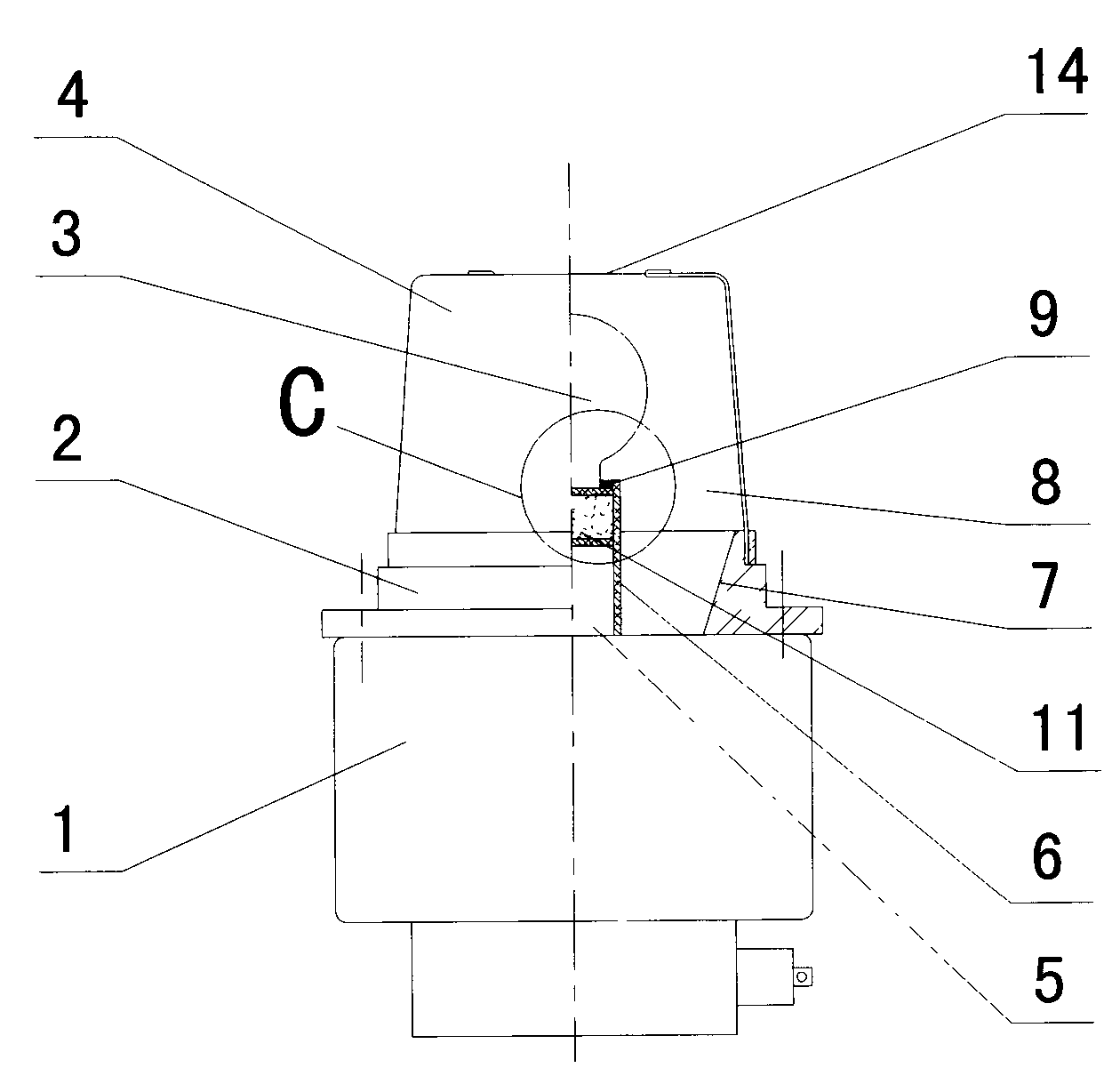
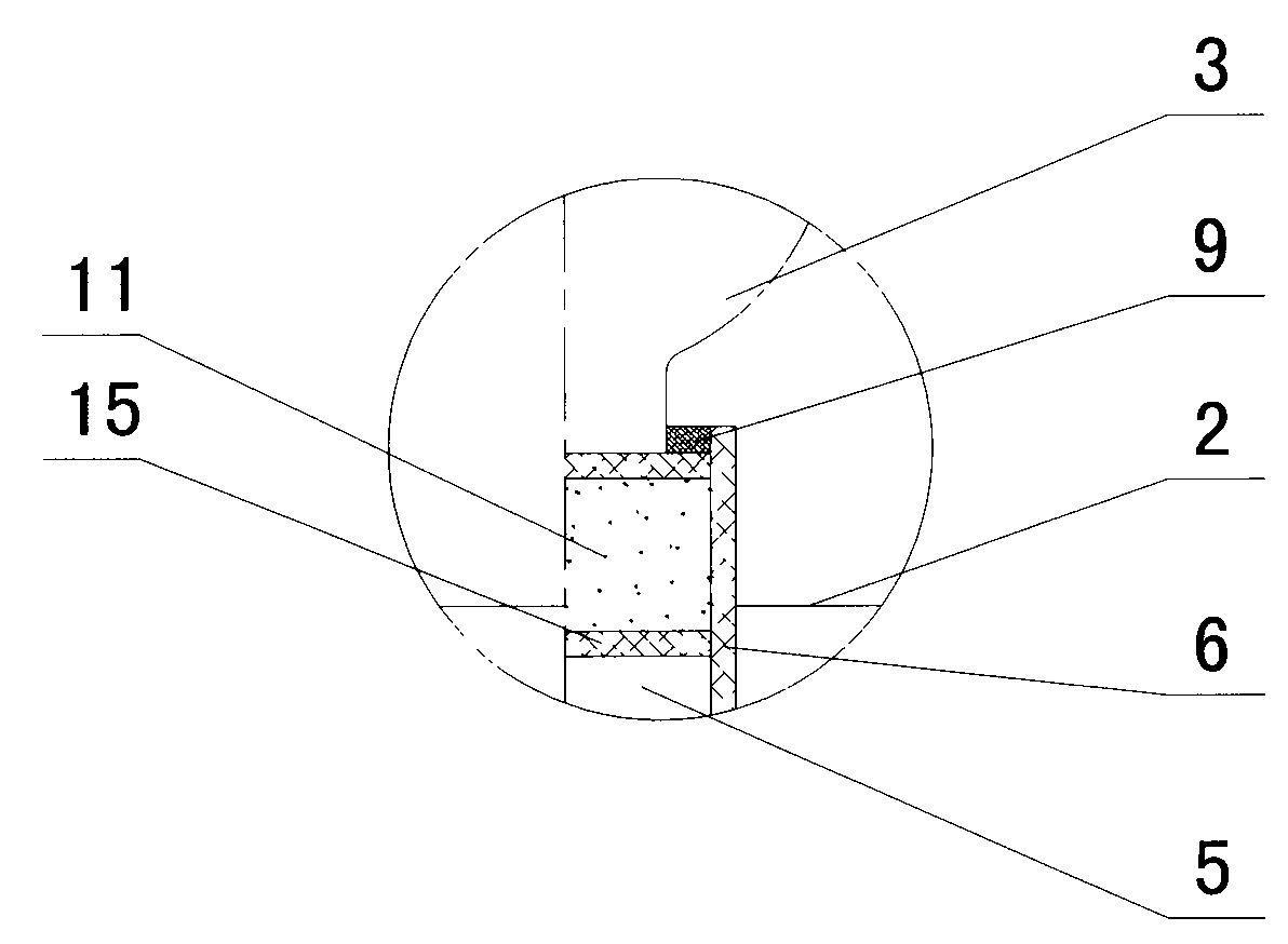
[0032] The first embodiment: as figure 1 and figure 2 , a coaxial resonant cavity microwave light source, comprising a magnetron 1 for generating microwaves, a magnetron antenna 5 connected to the magnetron 1, a conical waveguide fixed on the magnetron 1 and positioned at the periphery of the magnetron antenna 5 7. The shielding cover fixed on the conical waveguide 7, the magnetron antenna 5, the conical waveguide 7, and the shielding cover form a coaxial resonant cavity 8, and the coaxial resonant cavity 8 is equipped with a non-polar bulb 3, and the non-polar bulb 3 is a small quartz ball , the quartz ball is filled with luminescent substance and starting gas, the center lines of the electrodeless bulb 3, the conical waveguide 7, the magnetron antenna 5, and the shielding cover are all on the same central axis, and it is characterized in that:

[0033] The coaxial resonant cavity is a λ / 4 coaxial resonant cavity;

[0034] A light-transmitting hole 14 is opened on the top ...

no. 2 example

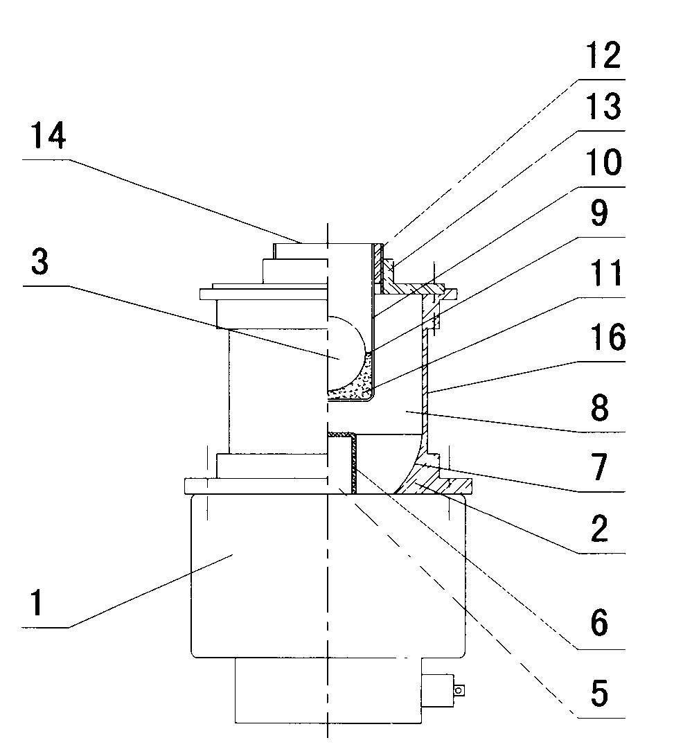
[0039] The second embodiment: as image 3 , a coaxial resonant cavity microwave light source, comprising a magnetron 1 for generating microwaves, a magnetron antenna 5 connected to the magnetron 1, a conical waveguide fixed on the magnetron 1 and positioned at the periphery of the magnetron antenna 5 7. The shielding cover fixed on the conical waveguide 7, the magnetron antenna 5, the conical waveguide 7, and the shielding cover form a coaxial resonant cavity 8, and the coaxial resonant cavity 8 is equipped with a non-polar bulb 3, and the non-polar bulb 3 is a small quartz ball , the quartz ball is filled with luminescent substance and starting gas, the center lines of the electrodeless bulb 3, the conical waveguide 7, the magnetron antenna 5, and the shielding cover are all on the same central axis, and it is characterized in that:

[0040] The coaxial resonant cavity is a λ / 4 coaxial resonant cavity;

[0041] A light-transmitting hole 14 is opened on the top of the shieldi...


PUM


Abstract

The invention provides a coaxial resonant cavity microwave light source which comprises a magnetron (1) for generating microwaves, a magnetron antenna (5) which is connected with the magnetron (1), a tapered waveguide (7) which is fixed on the magnetron (1) and is located at the periphery of the magnetron antenna (5), a shielding case which is fixed on the tapered waveguide (7) and a coaxial resonant cavity (8) which is formed by the magnetron antenna (5), the tapered waveguide (7) and the shielding case, wherein an electrodeless bulb (3) is arranged in the coaxial resonant cavity (8). The electrodeless bulb is a small quartz ball, and the small quartz ball is filled with luminescent substances and starting gas. The center lines of the electrodeless bulb (3), the tapered waveguide (7), the magnetron antenna (5) and the shielding case are at the same central axis line. The coaxial resonant cavity microwave light source is characterized in that the coaxial resonant cavity is a lambada / 4 coaxial resonant cavity; a light hole (14) is formed at the top of the shielding case, and the center of the light hole (14) is located on the central axis line. The shielding case is a mesh shielding case (4) or a non mesh shielding case (16).

Description

1. Technical field [0001] The invention relates to the field of electrodeless lamp electric light sources, in particular to a microwave plasma light source technology. 2. Background technology [0002] In 1994, the 3400W high-power microwave sulfur lamp (electrodeless lamp) invented by the Americans came out. Because this new type of light source has high light efficiency, energy saving, environmental protection, and the color similar to sunlight, it once caused a sensation in the lighting industry. The lamp is full of international markets. At the beginning of the 20th century, dozens of enterprises in my country successively launched high-power microwave sulfur lamps above 1000W, but up to now, the production and use of high-power microwave sulfur lamps have dropped significantly. Trace it to its cause, mainly because reasons such as poor safety and reliability of high-power microwave sulfur lamps, high price, short life-span hinder the popularization and use of this lamp...

Claims


Application Information

Patent Timeline
Patent Type & Authority Applications(China)
IPC IPC(8): H01J65/04
Inventor 李碧霞张雷雷彩云金行星
Owner 李碧霞
Why Eureka
Try Eureka