Electric dipole antenna and use method thereof

An electric dipole and antenna technology, which can be applied to folded antennas, resonant antennas, and mid-position feeding between antenna endpoints, etc., can solve the problems of low tuning range, limited clinical application, deterioration of signal-to-noise ratio, etc. Detection depth and detection area, improve transmission efficiency, improve the effect of signal-to-noise ratio

Active Publication Date: 2014-07-09
SHANGHAI UNITED IMAGING HEALTHCARE
View PDF4 Cites 8 Cited by
  • Summary
  • Abstract
  • Description
  • Claims
  • Application Information

AI Technical Summary

Problems solved by technology

At the same time, due to the high dielectric constant medium that causes a lot of load-bearing pressure on the detection object, the mechanical installation is difficult, and it is only suitable for research, not for production, and not suitable for clinical use.
Furthermore, the research on the ideal current distribution is to detect the current distribution on the surface of the object, and the high dielectric constant medium needs to place the electric dipole antenna in the far field, which cannot meet the conditions of the optimal current distribution
[0005] In addition, although the electric dipole array proposed by Graham Wiggins et al. avoids the use of high dielectric constant media, the electric dipole antenna can be located on the surface of the detection object, but after the design, the length of the electric dipole antenna cannot be changed, only The frequency tuning is performed by the inductance in the matching circuit of the transmitting / receiving port, the tuning range is low, and the use of the inductance increases the loss of the antenna and deteriorates the signal-to-noise ratio
Moreover, the resonant frequency of the electric dipole antenna it uses is very sensitive to the surrounding environment. With the difference of the distance between the detector and the detection object, the resonant frequency changes greatly. The distance changes by 1 cm, and the frequency change is greater than 5MHz, which is far beyond The acceptable frequency dynamic range of the magnetic resonance system limits its clinical application
In summary, there is currently no magnetic resonance electric dipole antenna suitable for clinical use

Method used


Image

  • Electric dipole antenna and use method thereof
  • Electric dipole antenna and use method thereof
  • Electric dipole antenna and use method thereof

Examples


Embodiment Construction

[0037] In the following description, numerous specific details are set forth in order to provide a thorough understanding of the present invention. However, the present invention can be implemented in many other ways different from those described here, and those skilled in the art can make similar extensions without violating the connotation of the present invention, so the present invention is not limited by the specific implementations disclosed below.

[0038] Secondly, the present invention is described in detail by means of schematic diagrams. When describing the embodiments of the present invention in detail, for convenience of explanation, the schematic diagrams are only examples, which should not limit the protection scope of the present invention.

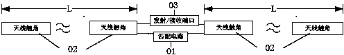
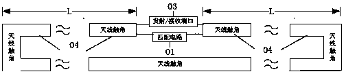
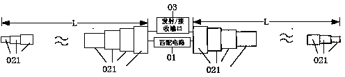
[0039] The invention provides an electric dipole antenna, comprising: an antenna antenna, a matching circuit and a transmitting / receiving port, the matching circuit is connected in parallel to both ends of the transmitting...


PUM


Abstract

The invention provides an electric dipole antenna which includes antenna feelers, and a match circuit and a transmission / reception port, both of which are connected with the antenna feelers. The lengths of the antenna feelers are adjusted through manual operation or an adjustment structure. The invention also provides a use method of the electric dipole antenna. The length of the electric dipole antenna can be adjusted so that the resonance frequency can be adjusted according to the difference of detection objects or difference of positions relative to the detection objects and thus the resonance frequency is at a work frequency. Therefore, a problem that an electric dipole antenna in the prior magnetic resonance system cannot be tuned or the tuning range is small and leads to extra loss is solved. Therefore, the electric dipole antenna is stable in work and applicable to clinical application of a high-field magnetic resonance system.

Description

[0001] technical field [0002] The invention relates to the field of medical equipment, in particular to an electric dipole antenna and a method for using the same. Background technique [0003] Recent studies have shown that in high-field magnetic resonance systems, traditional radio frequency body coils and surface coils cannot meet the requirements of obtaining the best signal-to-noise ratio at the center of the detected object, and it is necessary to introduce a detection device with an unclosed current path, that is, an electric dipole The sub-antenna can obtain the most ideal current distribution. And in the high field, the deflection caused by the dielectric constant of the detected object in the transmitting field and receiving field of the electric dipole antenna is small, so the penetration depth is large. In this case, a variety of electric dipole antennas have appeared in the field of magnetic resonance in recent years, such as the single-side adapted dipole...

Claims


Application Information

Patent Timeline
Patent Type & Authority Applications(China)
IPC IPC(8): H01Q9/16H01Q1/10H01Q1/36
Inventor 张蓓
Owner SHANGHAI UNITED IMAGING HEALTHCARE
Why Eureka
Try Eureka