Quenching equipment for completing quenching, isothermal treatment or tempering in same slot by transferring through hanging basket

A technology of quenching equipment and hanging basket, applied in the field of heat treatment equipment, can solve the problems of investment cost, high operating cost, severe corrosion, serious deformation, complex equipment structure, etc. Effect

Active Publication Date: 2014-07-16
TANGSHAN YAJIE MACHINERY
View PDF3 Cites 19 Cited by
  • Summary
  • Abstract
  • Description
  • Claims
  • Application Information

AI Technical Summary

Problems solved by technology

[0002] At present, the heat treatment equipment for workpieces such as bearing rings and ring gears are mostly heated by rollers or mesh belt furnaces, and then quenched in the quenching tank with rollers or mesh belts, and then enter the rollers or mesh belts for air cooling and cleaning equipment , into the roller or mesh belt furnace for isothermal or tempering, the existing problems are: ① Due to the heat transferred from the quenching of the workpiece to the quenching salt tank, the temperature of the salt bath in the quenching salt tank increases, and it is necessary to configure a fan or other methods to control the temperature of the quenching salt tank. The salt liquid is cooled, and the heat is discharged into the atmosphere, and the isothermal furnace (sa

Method used


Image

  • Quenching equipment for completing quenching, isothermal treatment or tempering in same slot by transferring through hanging basket
  • Quenching equipment for completing quenching, isothermal treatment or tempering in same slot by transferring through hanging basket
  • Quenching equipment for completing quenching, isothermal treatment or tempering in same slot by transferring through hanging basket

Examples


Embodiment Construction

[0033] The present invention will be further described below in conjunction with the examples, and the purpose is only to better understand the content of the present invention. Therefore, the examples given do not limit the protection scope of the present invention.

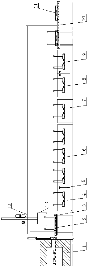
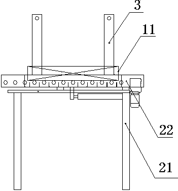
[0034] see figure 1 , the quenching equipment that completes quenching, isothermal or tempering in the same tank with hanging basket transfer described in this embodiment is composed of a heating furnace 1, a discharge table 2, a hanging basket 3, a quenching tank 4, an isothermal tank 6, an air-cooled Tank 7, salt water cleaning tank 8, clean water cleaning tank 9, unloading table 10, transfer manipulator 12, retrieving hook 13, wherein, quenching tank 4, isothermal tank 6, air cooling tank 7, salt water cleaning tank 8, clean water cleaning Groove 9 is arranged sequentially from discharge platform 2 to discharge platform 10, and transfer manipulator 12 is arranged on the top between discharge platform 2 and d...


PUM


Abstract

The invention relates to thermal treatment equipment and specifically relates to quenching equipment for completing quenching, isothermal treatment or tempering in the same slot by transferring through a hanging basket. The quenching equipment comprises a heating furnace, a discharging table, a quenching slot, an isothermal slot, an air-cooling slot, a saline water cleaning slot, a clear water cleaning slot and an unloading table, wherein the quenching slot, the isothermal slot, the air-cooling slot, the saline water cleaning slot and the clear water cleaning slot are arranged between the discharging table and the unloading table in sequence; the quenching slot and the isothermal slot are formed by dividing a liquid-connected large slot through an adjustable baffle plate; a transfer mechanical hand is arranged above the discharging table and the unloading table; a material taking hook of the transfer mechanical hand is equipped with the hanging basket for hanging and transferring workpieces. The quenching equipment disclosed by the invention can sufficiently utilize heat energy and lower thermal treatment process cost; by adopting a mode that liquid transfers heat for workpieces, tempering and isothermal temperatures of workpieces are more uniform, and better thermal treatment effect is obtained; the mechanical hand can realize automatic transfer of workpieces in different working media, and can realize various quenching processes.

Description

technical field [0001] The invention relates to heat treatment equipment, in particular to a quenching equipment which is transferred in the same tank by a hanging basket to complete quenching, isothermal or tempering. Background technique [0002] At present, the heat treatment equipment for workpieces such as bearing rings and ring gears are mostly heated by rollers or mesh belt furnaces, and then quenched in the quenching tank with rollers or mesh belts, and then enter the rollers or mesh belts for air cooling and cleaning equipment , into the roller or mesh belt furnace for isothermal or tempering, the existing problems are: ① Due to the heat transferred from the quenching of the workpiece to the quenching salt tank, the temperature of the salt bath in the quenching salt tank increases, and it is necessary to configure a fan or other methods to control the temperature of the quenching salt tank. The salt liquid is cooled, and the heat is discharged into the atmosphere, a...

Claims


Application Information

Patent Timeline
IPC IPC(8): C21D1/63
Inventor 戚顺银李振明
Owner TANGSHAN YAJIE MACHINERY
Why Eureka
Try Eureka