Combined heat exchange system

A heat exchange system and combined technology, applied in the direction of heat exchanger type, indirect heat exchanger, lighting and heating equipment, etc., can solve the problem of large area, easy cracking safety accident, large pressure drop loss of heat exchanger, etc. problems, to achieve the effect of small pressure drop loss, less expansion and cracking, small flow resistance and resistance

Active Publication Date: 2014-07-16
NANJING GOODCHINA CHEM TECH
View PDF9 Cites 0 Cited by
  • Summary
  • Abstract
  • Description
  • Claims
  • Application Information

AI Technical Summary

Problems solved by technology

[0004] The purpose of the present invention is to provide a combined heat exchange system to solve the technical problems of the heat exchanger in the high temperature heat recovery system in the prior art, such as large pressure drop loss, large footprint, easy cracking and safety accidents

Method used


Image

  • Combined heat exchange system
  • Combined heat exchange system
  • Combined heat exchange system

Examples


Embodiment 1

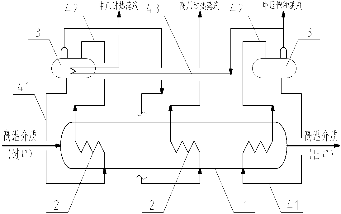
[0026] The system flow of Embodiment 1 of the present invention is as figure 1 As shown, the combined heat exchange system of this embodiment includes a shell 1 with a high-temperature medium inlet at one end and a high-temperature medium outlet at the other end. The inner wall of the shell 1 is provided with a heat insulating material, and the shell 1 is provided with a There are three heat exchange tube bundles 2 distributed sequentially in the flow direction of the high-temperature medium. There are two steam drums 3 connected to the heat exchange tube bundles 2 through pipes outside the shell 1. The temperature of the first steam drum is higher than that of the second steam drum. temperature, a downcomer 41 is provided between the first steam drum and the inlet of the first heat exchange tube bank, and a riser 42 is provided between the outlet of the first heat exchange tube bank and the first steam drum, so that the first steam drum and the first heat exchange tube bank c...

Embodiment 2

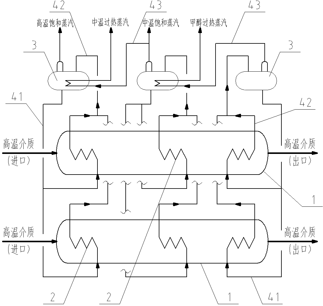
[0031] The system flow of embodiment 2 of the present invention is as figure 2As shown, the combined heat exchange system of this embodiment includes a shell 1 with a high-temperature medium inlet at one end and a high-temperature medium outlet at the other end. In this embodiment, the number of shells 1 is two, which is suitable for recycling multiple series of high-temperature For the heat of the medium, the inner wall of each shell 1 is equipped with heat insulating material, and each shell 1 is equipped with three heat exchange tube bundles 2 distributed in sequence along the flow direction of the high-temperature medium, and the shell 1 is equipped with passing pipes The three steam drums 3 connected with the heat exchange tube bundle 2, the temperature of the first steam drum is higher than the temperature of the second steam drum, and the temperature of the second steam drum is higher than the temperature of the third steam drum, different shells The heat exchange tube...

Embodiment 3

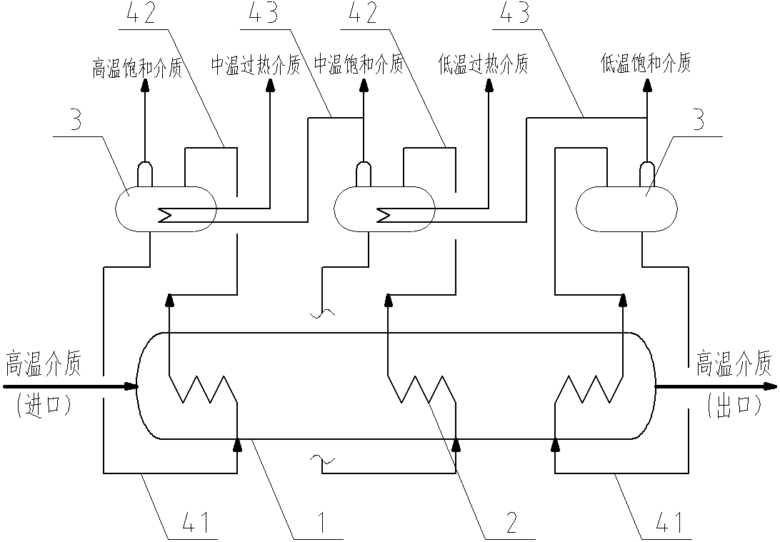
[0036] The system flow of embodiment 3 of the present invention is as image 3 As shown, the difference from Embodiment 2 of the present invention is that the number of shells in this embodiment is one, which is suitable for recovering the heat of a single series of high-temperature medium. The other structures of this embodiment are the same as those of Embodiment 3. Let me repeat.

[0037] Like Example 2, when this example is in use, the high-temperature medium flows in the shell, and part of the heat of the high-temperature medium is taken away by the medium in the heat exchange tube bank, and the medium in the first heat exchange tube bank is in the first cycle Finally, the heat of the medium in the first steam drum increases to obtain a high-temperature saturated medium, and the medium in the second heat exchange tube bank flows in the second cycle, and finally the heat of the medium in the second steam drum increases to obtain a medium Temperature-saturated medium, the ...


PUM


Abstract

The invention discloses a combined heat exchange system, and belongs to the technical field of high-temperature heat recovery systems. The combined heat exchange system comprises a shell, one end of the shell is provided with a high-temperature medium inlet, the other end of the shell is provided with a high-temperature medium outlet, a heat exchange pipe bundle is arranged in the shell, a steam pocket communicated with the heat exchange pipe bundle through a pipeline is arranged outside the shell, and the pipeline comprises a descending pipe communicated between the steam pocket and a heat exchange pipe bundle inlet and an ascending pipe communicated between a heat exchange pipe bundle outlet and the steam pocket. When a high-temperature medium flows in the shell, the heat exchange pipe bundle is communicated with the steam pocket to form natural circulation, a cooling medium in the heat exchange pipe bundle takes away a part of heat of the high-temperature medium, so that heat energy of the high-temperature medium is used fully, the flowing distance and the flowing resistance of the high-temperature medium are reduced, and pressure drop losses of the high-temperature medium are also reduced; in addition, due to the fact that the heat exchange pipe bundle is arranged in the shell, the heat exchange pipe bundle can expand freely, and the safety problem of cracking of the heat exchange system is avoided.

Description

technical field [0001] The invention relates to a heat exchange system, in particular to a combined heat exchange system used in heat recovery systems used in industries such as petrochemical, thermal power, metallurgy, and thermal energy engineering, and belongs to the technical field of high-temperature heat recovery systems . Background technique [0002] At present, in petrochemical, thermal power, metallurgy, thermal energy engineering and other industries, heat recovery systems are usually used to recycle the heat energy of high-temperature media. The heat recovery systems of such high-temperature media generally use single or multiple heat exchangers. Using a single heat exchanger to recover high-temperature heat energy has the advantages of fewer high-temperature medium pipelines and a small equipment footprint, but has the disadvantages of poor cascade comprehensive utilization of heat energy and low heat recovery efficiency; using multiple heat exchangers to recove...

Claims


Application Information

Patent Timeline
Patent Type & Authority Applications(China)
IPC IPC(8): F28D7/16
CPCY02P20/10
Inventor 张结喜吕帆肖陈长
Owner NANJING GOODCHINA CHEM TECH
Why Eureka
Try Eureka