Method for quickly measuring precision of reflection face of radiotelescope

A technology of radio telescopes and reflectors, applied in the direction of measuring electrical variables, measuring devices, instruments, etc., can solve problems such as unrealistic measurement, low reference antenna gain, and reduced antenna scanning efficiency

Inactive Publication Date: 2014-07-16
XINJIANG ASTRONOMICAL OBSERVATORY CHINESE ACADEMY OF SCI
View PDF5 Cites 11 Cited by
  • Summary
  • Abstract
  • Description
  • Claims
  • Application Information

AI Technical Summary

Problems solved by technology

[0008] 1. The gain of the reference antenna is low, and long-time integration is required. In order to calibrate the phase, it is necessary to periodically point to the signal source during the scanning process to obtain a phase reference, thereby reducing the scanning efficiency of the antenna and causing a long measurement time. question;
[0009] 2. Since the direct measurement of the phase distribution of the antenna aperture field requires a reference antenna and a correlator to obtain the reference phase, the complexity and hardware cost of the system are greatly increased;
[0010] 3. Since the gain of the reference antenna is too low, only geosynchronous satellites can be used as its signal source. In this case, the antenna pitch angle is a fixed value, and measurement at any pitch angle cannot be realized

Method used


Image

  • Method for quickly measuring precision of reflection face of radiotelescope
  • Method for quickly measuring precision of reflection face of radiotelescope
  • Method for quickly measuring precision of reflection face of radiotelescope

Examples


Embodiment Construction

[0042] Below in conjunction with the drawings, preferred embodiments of the present invention are given and described in detail.

[0043] The present invention, that is, a method for measuring the precision of a radio telescope reflector, comprises the following steps:

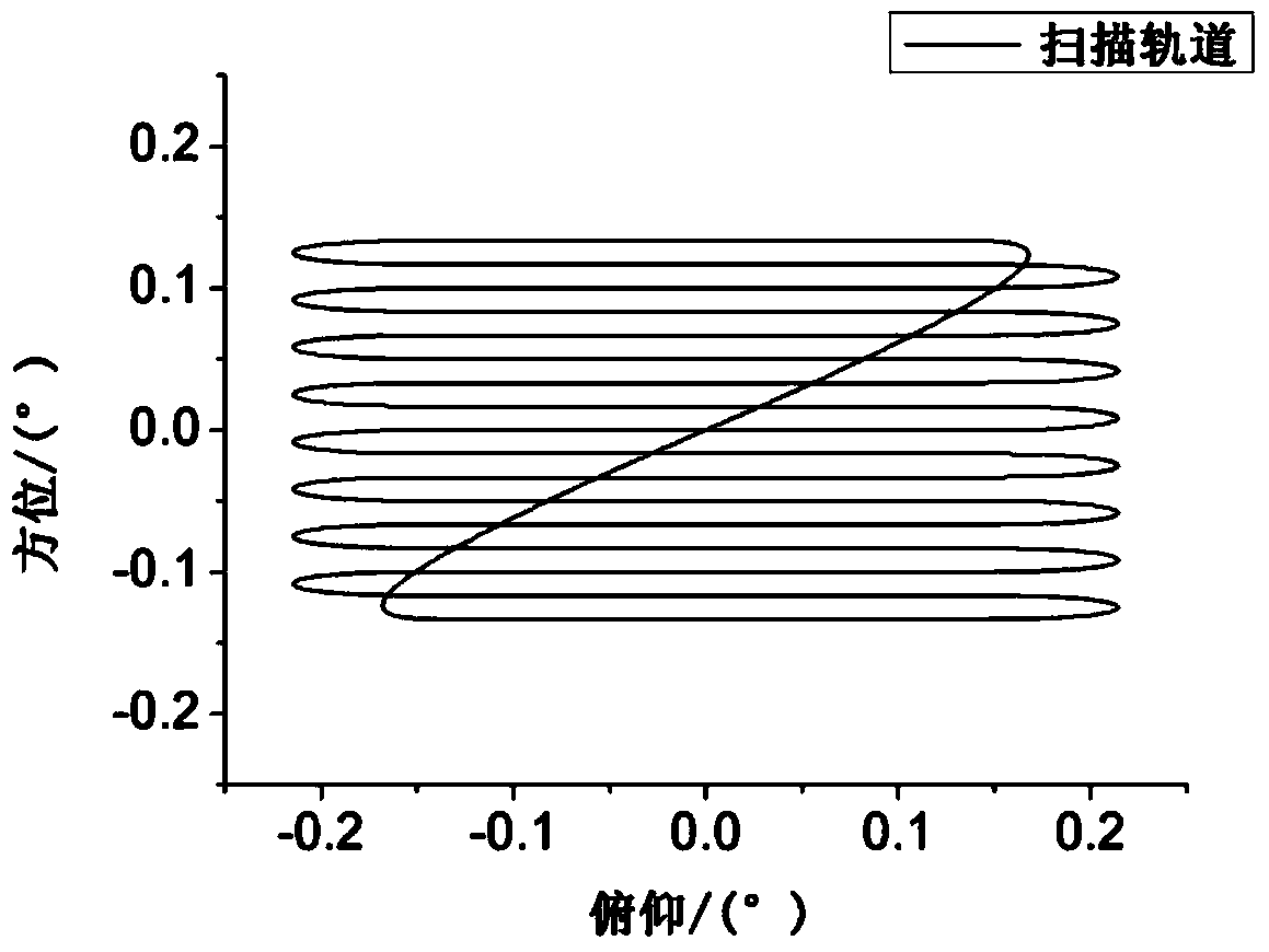
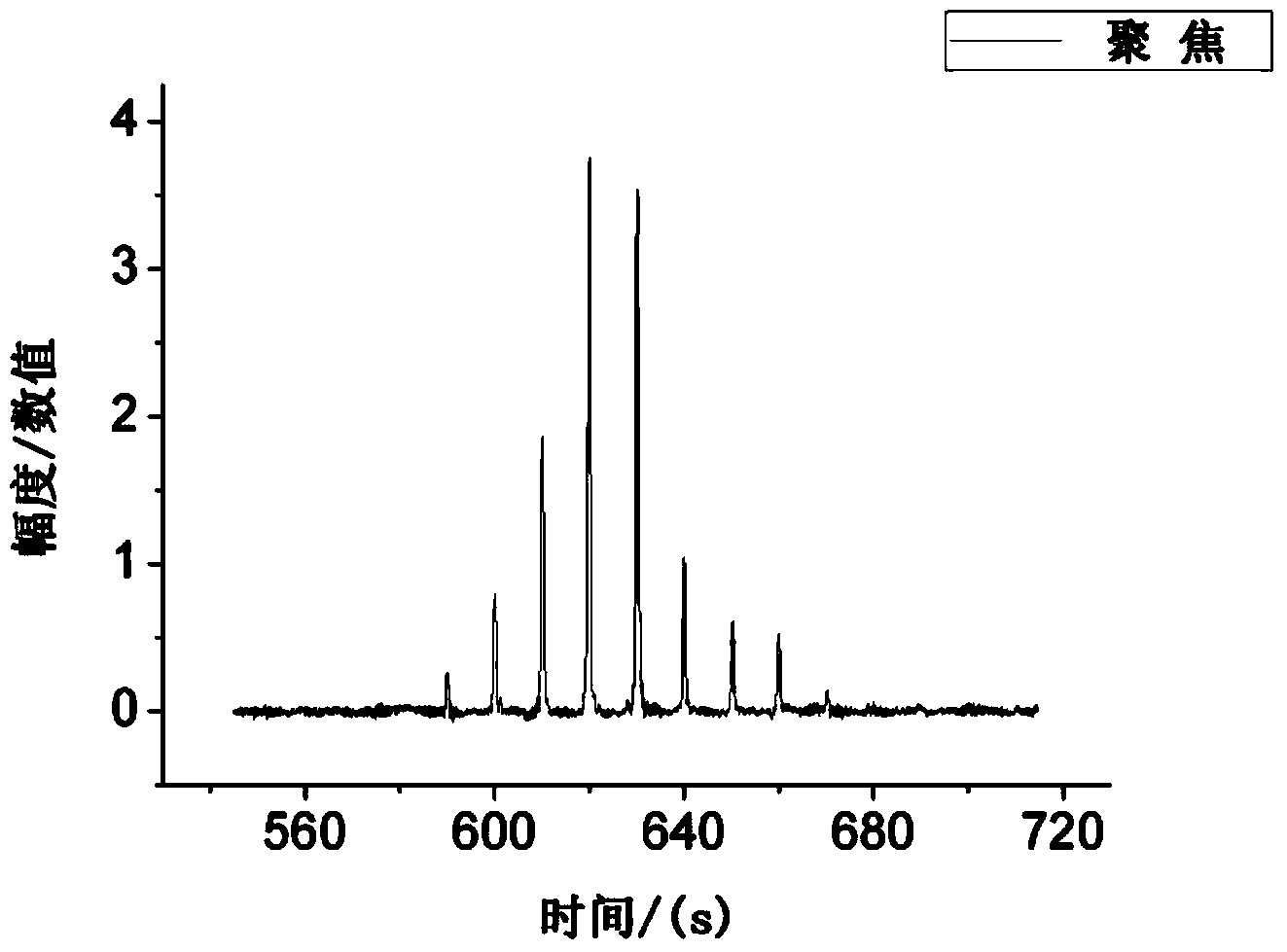
[0044] Step S1, observe the data once in the focused state of the radio telescope, and observe the data twice in the out-of-focus state. Each observation of data includes: using a radio astronomical source as a signal source, and making the radio telescope perform a grid scan around the signal source , at the same time record the position information of the radio telescope at this time (that is, the azimuth and elevation data of the radio telescope recorded during the observation, and the radio telescope will feed back these azimuth and elevation data during operation), and use the astronomical receiver to receive the scanned radio signals , and the astronomical terminal power radiometer records the amplitude ...


PUM


Abstract

The invention relates to a method for quickly measuring the precision of a reflection face of a radiotelescope. The method can effectively solve the problems that in the large-caliber radiotelescope reflection face precision measurement process, measurement time is long, measurement precision is low, the angle of pitch of measurement is fixed, and external hardware equipment is needed for assistance. According to the method as a special phase retrieval microwave holography method, it is only needed that the amplitude of an antenna aperture field is measured, and the retrieval of the phase of the antenna aperture field is carried out according to a certain method. In the method, any stable astronomical radio source can serve as a signal source, and beam patterns are scanned under the antenna focusing condition or the antenna out-of-focus condition through an astronomic receiving machine and a terminal (power radiometer); an antenna aperture phase model is built according to the Zernike polynomials function, iterative operation is carried out on the residual error of a model value and a measured value through the minimization algorithm, and therefore the optimal solution corresponding to the minimum residual error vector is obtained to obtain a Zernike polynomials coefficient, backstepping is carried out to obtain the hole aperture phase distribution of an antenna, and the precision of the reflection face of the radiotelescope can be obtained.

Description

technical field [0001] The invention relates to a method for quickly measuring the precision of a radio telescope reflection surface. Background technique [0002] The accuracy of the reflective surface of a radio astronomy telescope is an important indicator that affects its performance. It not only affects the observation efficiency of the radio telescope, but also determines the shortest wavelength that the radio telescope can work. In order to facilitate manufacturing and installation, the reflective surface (generally referred to as the main reflective surface) of a large-aperture radio telescope is usually spliced ​​by multiple single panels. During construction, electronic level installation, photogrammetry initial adjustment and microwave holographic fine adjustment can be used, etc. A series of technical means, so that the surface shape accuracy of the reflective surface of the radio telescope at a certain pitch angle can reach the design index. But when working, b...

Claims


Application Information

Patent Timeline
Patent Type & Authority Applications(China)
IPC IPC(8): G01R35/00
Inventor 裴鑫陈卯蒸刘志勇马军王娜
Owner XINJIANG ASTRONOMICAL OBSERVATORY CHINESE ACADEMY OF SCI
Why Eureka
Try Eureka